Lifting drainage well

A technology for drainage wells and drainage well covers, which is applied to drainage structures, water supply devices, waterway systems, etc., can solve problems such as poor drainage, easy blockage of drainage wells, and achieve the effect of rapid drainage.

Pending Publication Date: 2021-03-02
郝君
View PDF0 Cites 0 Cited by
  • Summary
  • Abstract
  • Description
  • Claims
  • Application Information

AI Technical Summary

Problems solved by technology

[0004] Therefore, the present invention provides a lifting drainage well to solve th

Method used


Image

  • Lifting drainage well
  • Lifting drainage well
  • Lifting drainage well

Examples


Embodiment

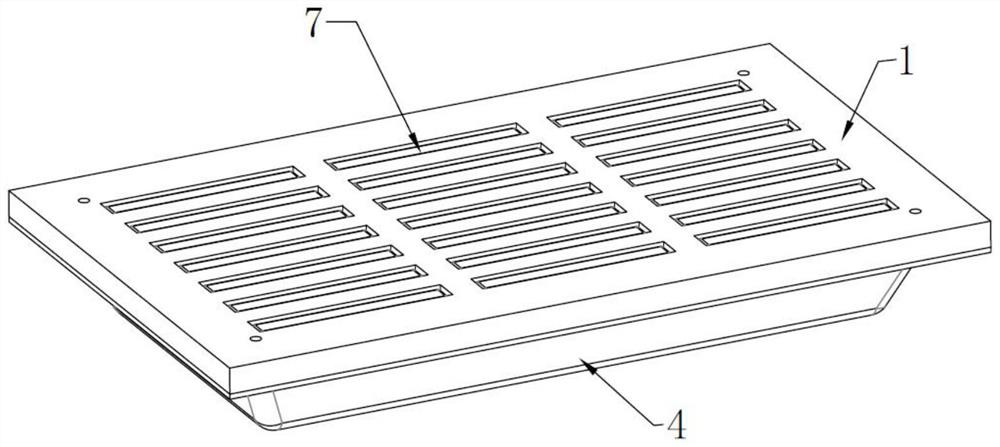
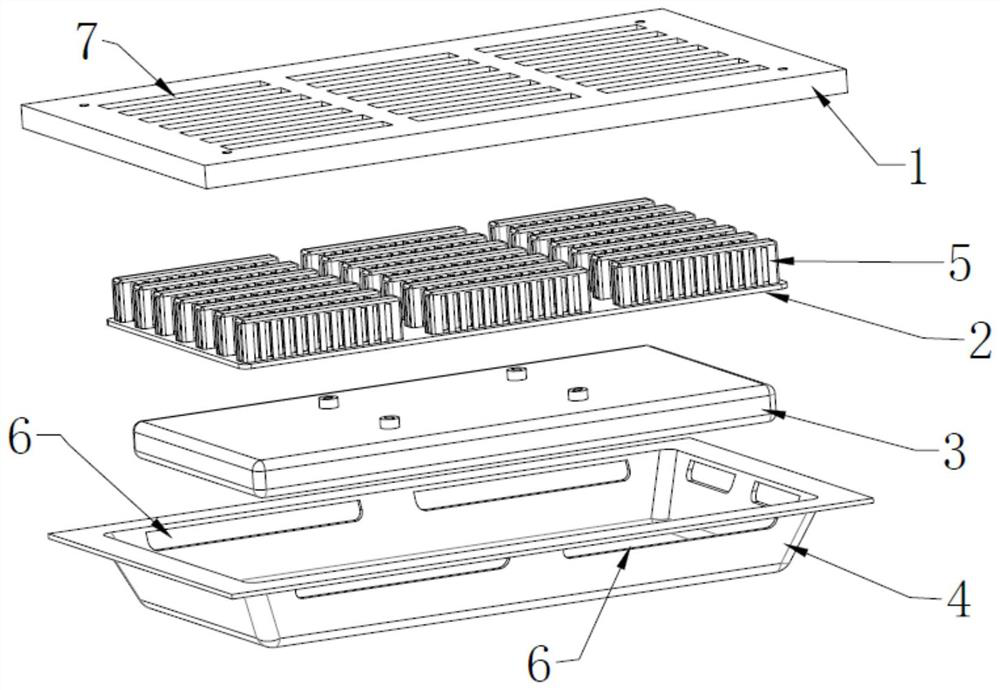
[0025] This embodiment discloses a lifting drainage well, which includes: a drainage well cover 1, a protective drainage cover 2, a buoyancy box 3 and a buoyancy tray 4, the buoyancy tray 4 is installed on the water outlet of the road surface, and the buoyancy tray 4 Inwardly recessed to form an accommodation cavity, the protective drainage cover 2 and the buoyancy box 3 are placed in the accommodation cavity of the buoyancy tray 4, the buoyancy box 3 is arranged on the bottom of the protective drainage cover 2 and is fixedly connected with the protective drainage cover 2, and the drainage well cover 1 is installed on the top of the buoyancy tray 4, and the top of the grille 5 of the protective drainage cover 2 coincides with the through hole of the drainage well cover 1.

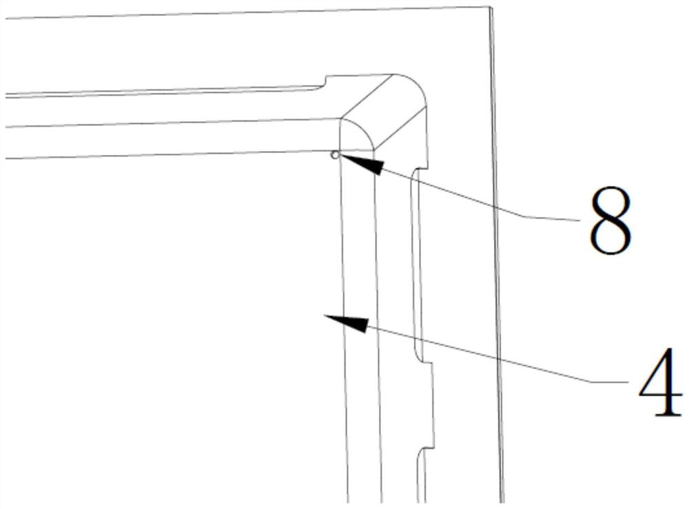
[0026] The four sides of the buoyancy tray 4 are all provided with drainage channels 6, and the four corners of the bottom of the buoyancy tray 4 are provided with drip holes 8, and the flow rate of dripping...


PUM


Abstract

The invention discloses a lifting drainage well. The lifting drainage well comprises a drainage well lid, a protective drainage cover, a buoyancy tank and a buoyancy tray. The buoyancy tray is installed at a water outlet of a road surface, the buoyancy tray is sunken inwards to form an accommodating cavity, and the protective drainage cover and the buoyancy tank are placed in the accommodating cavity of the buoyancy tray. The buoyancy tank is arranged at the bottom of the protective drainage cover and fixedly connected with the protective drainage cover, the drainage well lid is installed at the top of the buoyancy tray, and the top of a grid of the protective drainage cover coincides with a through hole of the drainage well lid. The problem that drainage is not smooth due to the fact thatan existing drainage well is prone to being blocked is solved.

Description

technical field [0001] The invention relates to the technical field of drainage, in particular to a lifting drainage well. Background technique [0002] Manhole covers are used to cover roads or deep wells in homes to prevent people or objects from falling, and are a common municipal road facility. According to the material, it can be divided into metal manhole covers, high-strength fiber cement concrete manhole covers, resin manhole covers, etc., generally round, and can be used for green belts, sidewalks, motorways, docks, alleys, etc. [0003] On city streets, manhole covers play an important role in dredging rainwater from the streets. Especially in the summer of our country, there is a lot of rain and a large amount of rainfall. If the precipitation on the streets is not removed in time, it will have a negative impact on the traffic in the city. Although the existing manhole cover can realize the rapid discharge of rainwater, garbage such as branches, leaves and plast...

Claims


Application Information

Patent Timeline
IPC IPC(8): E03F5/06E03F5/14E03F7/00
CPCE03F5/06E03F5/14E03F7/00E03F2005/068
Inventor 郝君
Owner 郝君
Why Eureka
Try Eureka