
Constant-pressure exhaust brake pressure-limiting valve

A technology of exhaust brake and pressure limiting valve, which is applied in the direction of engine control, machine/engine, mechanical equipment, etc., can solve problems such as spring failure, structure not described in detail, sideslip, etc., and achieve stable braking pressure and control Sensitive dynamic response and long service life

Pending Publication Date: 2021-03-02
WEICHAI POWER YANGZHOU DIESEL ENGINE
View PDF1 Cites 0 Cited by
  • Summary
  • Abstract
  • Description
  • Claims
  • Application Information

AI Technical Summary

Problems solved by technology

The simple brake valve does not have the function of ensuring a constant back pressure in the exhaust system of the engine. If the back pressure is too low, the exhaust brake valve will not be effective. Therefore, a pressure-limiting valve is connected to the exhaust brake valve. Common pressure-limiting valves use spring-type valve bodies. For example, the Chinese utility model patent with document number CN201679529U discloses a constant pressure exhaust brake valve The dynamic valve, whose specific structure is not described in detail, can obtain stable back pressure and stable braking force. However, since the high-temperature engine exhaust will pass through the spring, the spring will work at a long-term high temperature, and the spring will easily fail and reduce the Extends the service life of the entire auxiliary braking system

Method used


Image

  • Constant-pressure exhaust brake pressure-limiting valve
  • Constant-pressure exhaust brake pressure-limiting valve
  • Constant-pressure exhaust brake pressure-limiting valve

Examples


Embodiment Construction

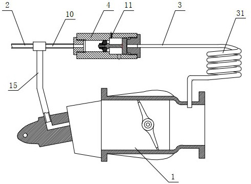
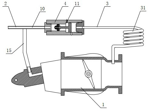
[0016] refer to figure 1 and figure 2 As shown, the present invention provides an embodiment of a constant pressure exhaust brake pressure limiting valve, for the convenience of description, with figure 1 The left and right directions in the figure are the front and rear directions of the present invention, and the left part is the front, which includes a brake valve 1 and a compressed air pipe 2, the front end of the brake valve 1 is connected to the compressed air pipe 2, and the rear end is connected to the exhaust pipe. The specific structure of the movable valve 1 is the prior art, which includes a valve body, the valve body is provided with a valve plate driven by a pneumatic mechanism, the front end of the valve body is connected to the above-mentioned compressed air pipe 2 through a pipeline, and the compressed air pipe is connected to the whole machine ( The compressed gas source (compression pump) of the engine or the whole vehicle), the rear end of the valve body ...


PUM


Abstract

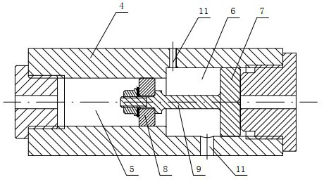
The invention discloses a constant-pressure exhaust brake pressure-limiting valve. The constant-pressure exhaust brake pressure-limiting valve comprises a brake valve and a compressed air pipe, the front end of the brake valve is connected to the compressed air pipe, the rear end of the brake valve is connected with an exhaust pipe, the rear end of the brake valve is further connected with an exhaust pressure passing pipe, and the exhaust pressure passing pipe is connected with a pressure-limiting valve body. A stepped inner cavity communicating with exhaust pressure passing pipe is formed inthe pressure limiting valve body, the stepped inner cavity is composed of a small-diameter cavity at the front end and a large-diameter cavity at the rear end, a large piston is connected into the large-diameter cavity in a sealed and sliding mode, a small piston is connected into the small-diameter cavity in a sealed and sliding mode, and a connecting rod is connected between the large piston andthe small piston. The pressure limiting valve body is connected with a balance pipe, the balance pipe communicates with a compressed air pipe, the large-diameter cavity communicates with exhaust pressure passing pipe, and two balance holes are formed in the large piston cavity. Exhaust back pressure can be guaranteed in real time, stable brake working pressure is guaranteed, and the constant-pressure exhaust brake pressure-limiting valve has the advantages of being sensitive in brake reaction, good in brake effect and long in service life.

Description

technical field [0001] The invention relates to a constant pressure exhaust brake pressure limiting valve. Background technique [0002] Automobile engine braking system is one of the important devices for safe driving of automobiles. The car's brakes are used when the vehicle needs to brake frequently when it needs to slow down. Most of the existing vehicles use traditional friction brakes. In the braking system, many vehicles are now equipped with exhaust brakes, that is, by limiting or reducing the cross-sectional area of ​​the engine exhaust pipeline, increasing the exhaust resistance, so that the engine Deceleration, so that the speed of the vehicle is reduced, and the exhaust brake is used as an auxiliary brake, which can effectively ensure the braking effect. The basic structure of the exhaust brake includes a brake valve installed on the exhaust pipeline. Since the exhaust brake is realized by using gas back pressure, that is, the brake is realized by the differenc...

Claims


Application Information

Patent Timeline
Patent Type & Authority Applications(China)
IPC IPC(8): F02D9/06
CPCF02D9/06
Inventor 王慧陈尚荣
Owner WEICHAI POWER YANGZHOU DIESEL ENGINE
Learn More