
Transient electromagnetic sleeve damage three-dimensional imaging method

A transient electromagnetic and three-dimensional imaging technology, which is applied in the fields of material magnetic variables, image data processing, and instruments, can solve the problems of three-dimensionally displaying the spatial position of the casing and cannot intuitively reflect the change of the inner diameter of the casing, so as to achieve intuitive and real Shape and position, improve the accuracy, and the effect of strong three-dimensional image

Pending Publication Date: 2021-03-02
CHINA PETROLEUM & CHEM CORP +1
View PDF0 Cites 1 Cited by
  • Summary
  • Abstract
  • Description
  • Claims
  • Application Information

AI Technical Summary

Problems solved by technology

However, because it displays the thinning, shrinkage, corrosion and leakage damage of the pipe wall through the magnitude of the induced electromotive force, it cannot fully and intuitively reflect the change of the inner diameter of the casing like a caliper. Described in two dimensions, cannot accurately interpret damage results
Since this technology cannot accurately, intuitively, and three-dimensionally display the spatial position of casing damage, it is necessary to conduct in-depth research on the interpretation method and establish an efficient TEM interpretation and inversion method

Method used


Image

  • Transient electromagnetic sleeve damage three-dimensional imaging method
  • Transient electromagnetic sleeve damage three-dimensional imaging method
  • Transient electromagnetic sleeve damage three-dimensional imaging method

Examples


Embodiment Construction

[0039] In order to make the above and other objects, features and advantages of the present invention more comprehensible, the preferred embodiments are listed below and shown in the accompanying drawings in detail as follows.

[0040] The present invention makes the two-dimensional data visually display its form in three dimensions by performing algorithmic correction and space regular arrangement.

[0041] 1. Read all the data of the casing measured by the electromagnetic flaw detector, and place the corresponding data under the corresponding name;

[0042] 2. Divide the measured casing damage data into regions so that the data are distributed in the specified regions;

[0043] 3. Set the threshold to remove the bad point data in the transient electromagnetic bushing damage data. To avoid the impact of the measured bad point data on the overall effect of 3D imaging;

[0044] 4. The depth data is corrected by the stretching algorithm so that it basically corresponds to the ...


PUM


Abstract

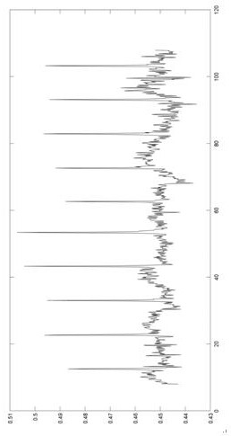
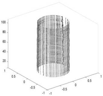
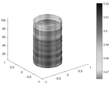
The invention provides a transient electromagnetic sleeve damage three-dimensional imaging method, which comprises the following steps: carrying out region division on sleeve damage data to enable thedata to be distributed in a specified region; performing scaling algorithm correction on the depth data; performing linear interpolation on the depth data; respectively selecting four curves from thedata measured by probes in four different directions, and storing the data at fixed named positions; separating the information of an inner wall and an outer wall of the measured curve; placing innerand outer wall information of the selected curve in a phase corresponding to the space according to the orientation of a probe of the curve; performing Hermite interpolation on the curve data in a three-dimensional space; and performing three-dimensional mesh generation on the data, and performing color spreading according to the size of the data, so that the size of the data is reflected throughcolor change. According to the transient electromagnetic sleeve damage three-dimensional imaging method, three-dimensional display of the casing damage is achieved, and the real form and position ofthe casing damage can be visually reflected.

Description

technical field [0001] The invention relates to the technical field of oilfield development, in particular to a three-dimensional imaging method for transient electromagnetic casing damage. Background technique [0002] With the deepening of oil and gas development in production wells, most oilfields in my country have entered the middle and late stages of exploration and development. Production well logging technology based on transient electromagnetic theory can obtain production well casing damage, which is very important for the sustainable development of oilfields. is of great significance. [0003] Transient electromagnetic detection uses a non-contact measurement method, which is suitable for logging in complex wellbore environments. However, because it displays the thinning, shrinkage, corrosion and leakage damage of the pipe wall through the magnitude of the induced electromotive force, it cannot fully and intuitively reflect the change of the inner diameter of the ...

Claims


Application Information

Patent Timeline
Patent Type & Authority Applications(China)
IPC IPC(8): G01N27/82G06T17/20
CPCG01N27/82G06T17/20
Inventor 安百新王昕车传睿刘红兰张国玉聂飞朋顾国利田俊宋辉辉
Owner CHINA PETROLEUM & CHEM CORP
Learn More