
Surface acoustic wave curve reflection stripe and touch screen applying same

A technology of reflection stripes and surface acoustic waves, which is applied in the field of surface acoustic wave curve reflection stripes and touch screens using the curve reflection stripes, can solve problems such as poor signals, reduce energy loss, reduce acoustic noise interference, and have strong penetrating ability Effect

Pending Publication Date: 2021-03-02
深圳市凯健奥达科技有限公司
View PDF4 Cites 0 Cited by
  • Summary
  • Abstract
  • Description
  • Claims
  • Application Information

AI Technical Summary

Problems solved by technology

[0005] The object of the present invention is to provide a surface acoustic wave curved reflection stripe and a touch screen using the curved reflection stripe, solve the scattering problem in the sound wave transmission, reduce the energy loss in the sound wave transmission and the noise caused by scattering, and solve the common reflection stripe. Used for poor signal problems in large-size touch screens

Method used


Image

  • Surface acoustic wave curve reflection stripe and touch screen applying same
  • Surface acoustic wave curve reflection stripe and touch screen applying same
  • Surface acoustic wave curve reflection stripe and touch screen applying same

Examples


Embodiment 1

[0032] Embodiment 1: A surface acoustic wave curved reflection stripe, which transforms the reflection stripe from a straight line into a curve or multi-curve segment, changes the reflection angle, converges the scattered sound waves, and passes the sound waves transmitted at different angles through the reflection angle The change of the sound wave adjusts the reflection path of the sound wave, thereby forming a reflected sound wave that propagates in a straight line and parallel.

[0033] Preferably, the reflection stripes are transformed from straight lines into curves or multi-curve segments in a specific way: setting the reflection stripes as one or more different curve parts, using different curve function fittings, and changing the reflection angle, The reflected wave is propagated parallel to the straight line; said different curve function fitting is used, the specific method is: according to the different distances of the reflected stripes from the transducer, differe...

Embodiment 2

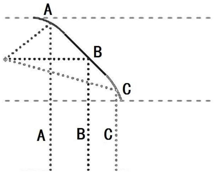
[0034] Embodiment 2: as figure 2 As shown, the difference from Example 1 is that the reflective stripes are set to a plurality of different curve parts, and the specific method is: the reflective stripes are set to three different curve parts of A, B and C (with three segment curve as an example). Use the curve fitting method to calculate the incident angles at different distances, change the fringe angles, and make the reflected waves A, B, and C propagate in parallel in a straight line.

Embodiment 3

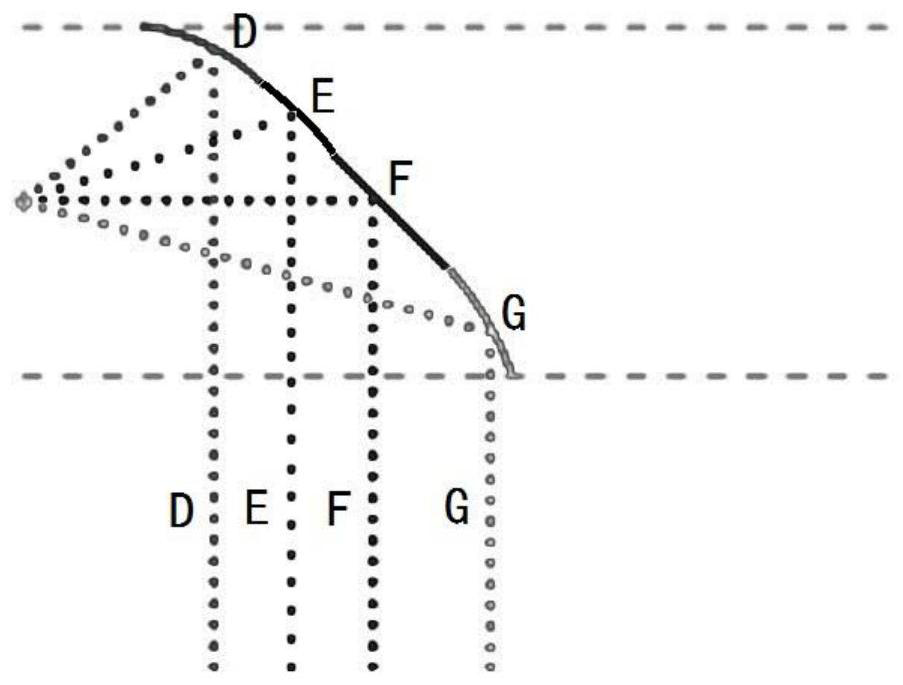
[0035] Embodiment 3: as image 3 As shown, the difference from Embodiment 1 is that the reflective stripes are set as a plurality of different curve parts, and the specific method is: set the reflective stripes as four different curve parts D, E, F, and G. Use the curve fitting method to calculate the incident angles at different distances, change the fringe angles, and make the reflected waves D, E, F, and G propagate in parallel in a straight line.


PUM


Abstract

The invention relates to a surface acoustic wave curve reflection stripe, which is characterized in that the reflection stripe is converted into a curve or multi-curve segment form from a straight line, a reflection angle is changed, scattered incident sound waves are converged, and a sound wave reflection path of the sound waves transmitted at different angles is adjusted through the change of the reflection angle, so that linearly and parallelly propagated reflection sound waves are formed. The problem of scattering in sound wave transmission is solved, energy loss in sound wave transmissionand noise generated by scattering are reduced, and the problem that signals are poor when common reflection stripes are used for a large-size touch screen is solved.

Description

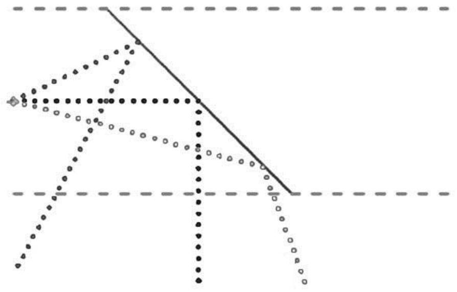
technical field [0001] The invention relates to the field of surface acoustic wave touch screens, in particular to a surface acoustic wave curved reflection stripe and a touch screen using the curved reflection stripe. Background technique [0002] The surface acoustic wave touch screen is mainly a device that uses the physical characteristics of ultrasonic waves propagating on the glass surface to realize touch position detection and positioning. The Chinese patent with authorized notification number CN2636331Y discloses an improved touch screen. The structure of the touch screen includes: screen body, surface acoustic wave transducer elements (transmitting transducer elements and receiving transducer elements) and reflective stripes arranged around the screen body . [0003] When sound waves pass through reflection stripes, there will be transmission processes such as penetration and reflection; figure 1 As shown, the traditional reflective stripes use a straight line de...

Claims


Application Information

Patent Timeline
Patent Type & Authority Applications(China)
IPC IPC(8): G06F3/043
CPCG06F3/0433
Inventor 李荣尧蒋昭林
Owner 深圳市凯健奥达科技有限公司
Learn More