
Localization punching system and method for joint replacement surgery

A technology for joint replacement and surgery, applied in the fields of surgery, application, medical science, etc., can solve the problems of inaccurate determination of the position of the center point, poor matching degree of transplantation, and low performance of equipment.

Inactive Publication Date: 2018-12-25
QINGDAO MUNICIPAL HOSPITAL
View PDF9 Cites 0 Cited by
  • Summary
  • Abstract
  • Description
  • Claims
  • Application Information

AI Technical Summary

Problems solved by technology

[0004] Traditional joint replacement surgery has a large error in positioning and drilling, and cannot accurately determine the position of the center point; at the same time, for irregular joint injuries, the transplantation matching degree is poor
[0005] The existing positioning and drilling methods for joint replacement surgery have a low degree of intelligence, and the accuracy of the obtained data is poor, resulting in low performance of the equipment

Method used


Image

  • Localization punching system and method for joint replacement surgery
  • Localization punching system and method for joint replacement surgery
  • Localization punching system and method for joint replacement surgery

Examples


Embodiment Construction

[0088]为了使本发明的目的、技术方案及优点更加清楚明白,以下结合实施例,对本发明进行进一步详细说明。应当理解,此处所描述的具体实施例仅仅用以解释本发明,并不用于限定本发明。

[0089]下面结合附图及具体实施例对本发明的应用原理作进一步描述。

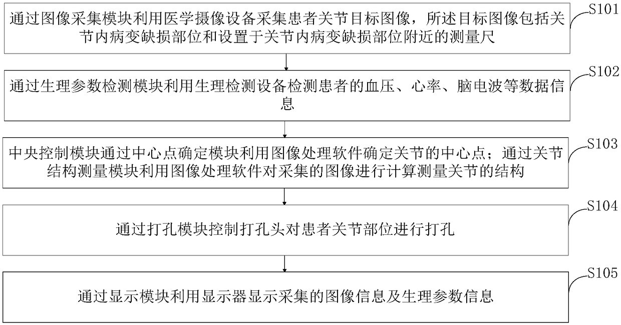
[0090]如图1所示,本发明提供的一种用于关节置换手术的定位打孔方法包括以下步骤:

[0091]S101,通过图像采集模块利用医学摄像设备采集患者关节目标图像,所述目标图像包括关节内病变缺损部位和设置于关节内病变缺损部位附近的测量尺;

[0092]S102,通过生理参数检测模块利用生理检测设备检测患者的血压、心率、脑电波等数据信息;

[0093]S103,中央控制模块通过中心点确定模块利用图像处理软件确定关节的中心点;通过关节结构测量模块利用图像处理软件对采集的图像进行计算测量关节的结构;

[0094]S104,通过打孔模块控制打孔头对患者关节部位进行打孔;

[0095]S105,通过显示模块利用显示器显示采集的图像信息及生理参数信息。

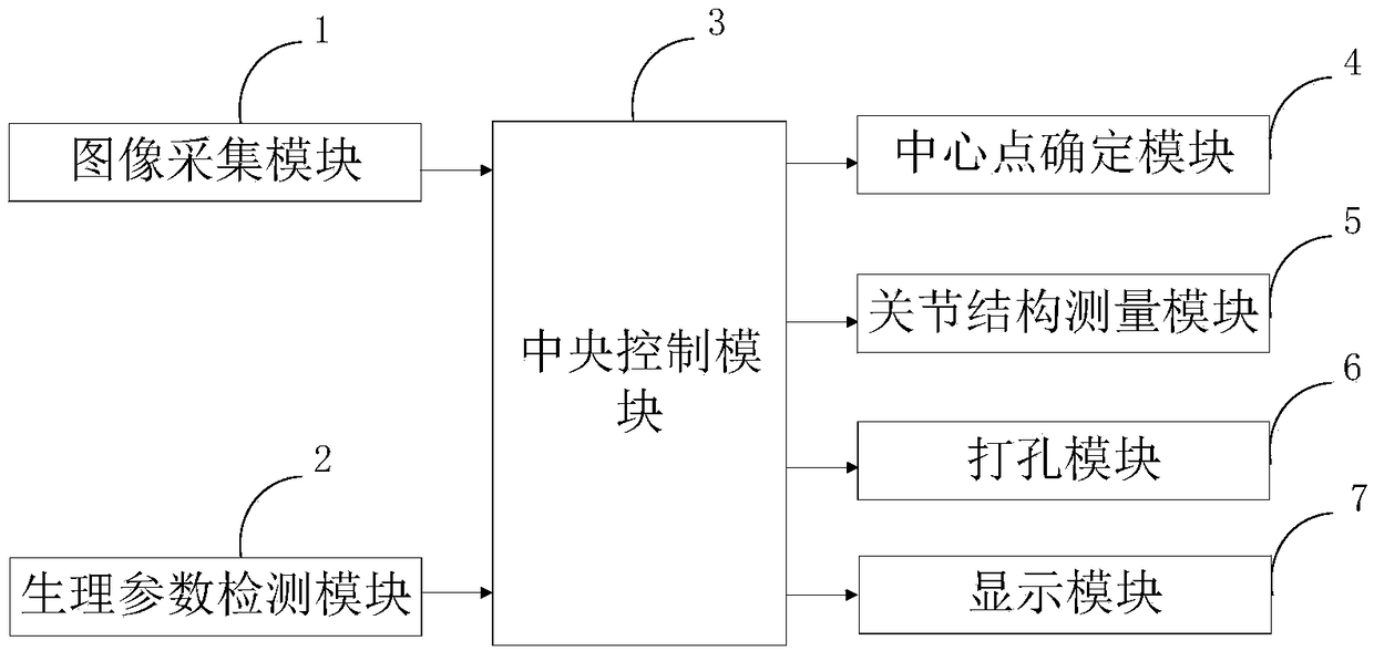
[0096]如图2所示,本发明提供的用于关节置换手术的定位打孔系统包括:图像采集模块1、生理参数检测模块2、中央控制模块3、中心点确定模块4、关节结构测量模块5、打孔模块6、显示模块7。

[0097]图像采集模块1,与中央控制模块3连接,用于通过医学摄像设备采集患者关节目标图像,所述目标图像包括关节内病变缺损部位和设置于关节内病变缺损部位附近的测量尺;

[0098]生理参数检测模块2,与中央控制模块3连接,用于通过生理检测设备检测患者的血压、心率、脑电波等数据信息;

[0099]中央控制模块3,与图像采集模块1、生理参数检测模块2、中心点确定模块4、关节结构测量模块5、打孔模块6、显示模块7连接,用于通过单片机控制各个模块正常工作;

[0100]中心点确定模块4,与中央控制模块3连接,用于通过图像处理软件确定关节的中心点;

[0101]关节结构测量模块5,与中央控制模块3连接,用于通过图像处理软件对采集的图像进行计算测量关节的结构;

[0102]打孔模块6,与中央控制模块3连接,用于通过控制打孔头对患者关节部位进行打孔;

[0103]显示模块7,与中央控制模块3连接,用于通过显示器显示采集的图像信息及生理参数信息。

[0104]本发明提供的中心点确定模块4方法如下:

[0105]首先,将采集的关节图像进行三维重建;...


PUM


Abstract

The invention belongs to the technical field of medical joint replacement, and discloses a positioning punching system and method for joint replacement surgery. The positioning punching system for joint replacement surgery comprises an image acquisition module, a physiological parameter detection module, a central control module, a central point determination module, a joint structure measurementmodule, a punching module and a display module. The center point of joint is determined by the center point determination module in three-dimensional space, and the two-dimensional data obtained by the traditional method, such as X-ray, CT, MRI and other imaging materials and the cadaver specimens are used for locating the center point of joint, and the accuracy is higher. The core stress zone isbetter concentrated to measure and determine the joint center point, and the system better conforms to the measurement of lower limb force lines; meanwhile, the joint structure measurement module is used for for irregular shape joint injuries, and grafted plants and joint injuries can be accurately matched.

Description

technical field [0001] The invention belongs to the technical field of medical joint replacement, and in particular relates to a positioning drilling system and method for joint replacement surgery. Background technique [0002] The connection between bone and bone is called bone connection. Bone connection is divided into direct connection and indirect connection, and joint is a form of indirect connection. Generally, it consists of three parts: articular surface, joint capsule and joint cavity. The articular surface is the contact surface of two or more adjacent bones, one is slightly convex, called the articular head, and the other is slightly concave, called the articular fossa. The articular surface is covered with a layer of smooth cartilage, which can reduce friction during exercise. Cartilage is elastic and can also slow down vibration and impact during exercise. The joint capsule is a kind of tough connective tissue that firmly connects two adjacent bones. The o...

Claims


Application Information

Patent Timeline
IPC IPC(8): A61B17/16A61B17/17A61B5/0205A61B5/0476
CPCA61B5/0205A61B17/1604A61B17/1703A61B5/369
Inventor 胡光亮马振华徐迈
Owner QINGDAO MUNICIPAL HOSPITAL
Learn More