
A LED high-speed crystal-bonding equipment and its automatic loading and unloading device

A technology of crystal bonding and equipment, applied in the field of LED high-speed crystal bonding equipment and its automatic loading and unloading device, can solve the problems of low LED preparation efficiency and affecting LED output, so as to improve the actual application effect, improve the crystal bonding efficiency, increase the Effect of degree of particle dispersion

Active Publication Date: 2021-09-07
YANCHENG DONGSHAN PRECISION MANUFACTURING CO LTD
View PDF16 Cites 0 Cited by
  • Summary
  • Abstract
  • Description
  • Claims
  • Application Information

AI Technical Summary

Problems solved by technology

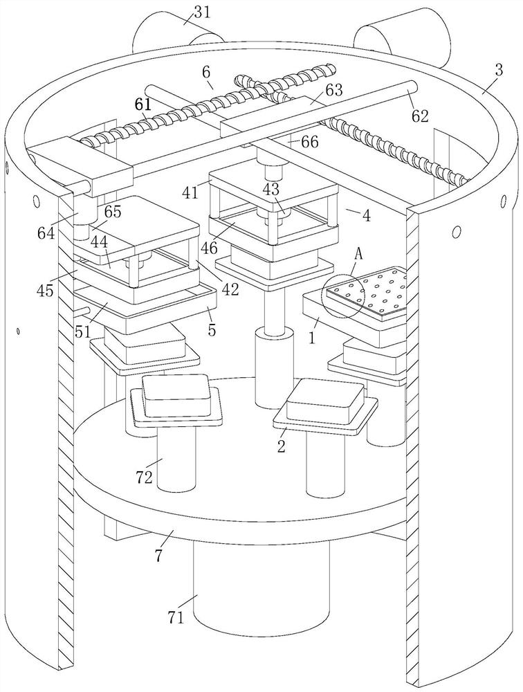
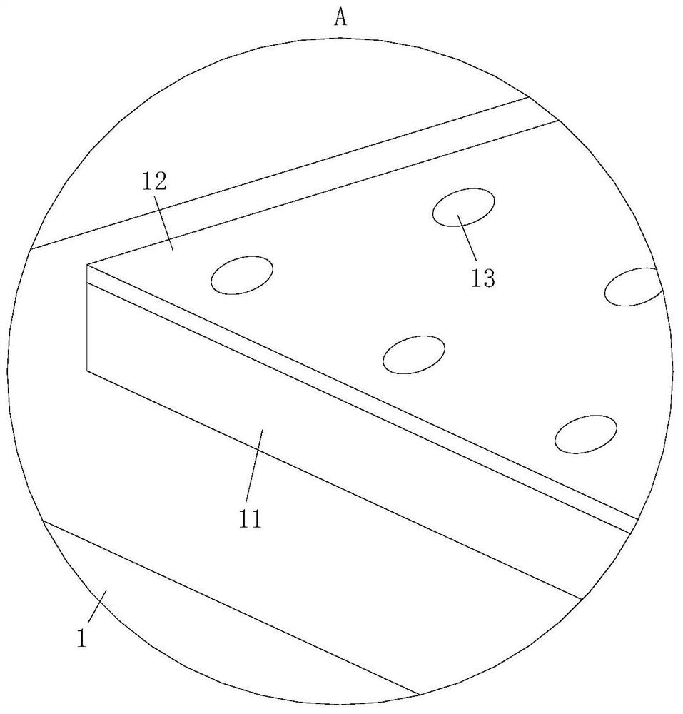
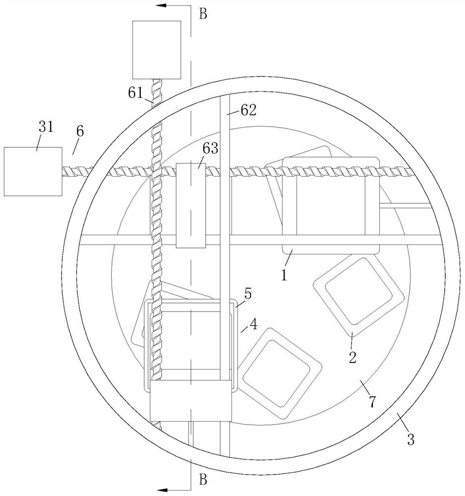
[0007] During work, the existing die-bonding is to carry out crystal-bonding to one of the chips first, and then carry out crystal-bonding to the other chip, which causes the problem of low LED preparation efficiency and affects the output of LEDs; therefore, in the present invention, the staff starts the controller Control the rotation of one of the No. 1 motors, and the No. 1 motor drives the corresponding screw slider pair to move, so that the screw slider pair drives one of the injection units to move to the top of the dispensing plate, and the No. 1 electric push rod drives The lower end of the injection plate is close to the upper surface of the adhesive, and the controller controls the cylinder to drive the push plate to slide upward along the groove, thereby sucking the adhesive into the groove, and the No. 1 electric push rod drives the injection plate away from the point Rubber plate, one of the screw sliders drives the injection unit to move to the top of the fixture console, and at the same time ensures that the suction nozzle corresponds to the core setting table one by one. The No. 1 electric push rod drives the suction nozzle close to the core setting table, and the push plate Slide down along the groove, so that the adhesive is squeezed on the core setting table along the suction nozzle, and then the No. 1 electric push rod drives the suction nozzle away from the core setting table, and one of the screw sliders drives the injection unit Away from the fixture console; the controller controls another No. 1 motor to rotate, and the other No. 1 motor drives another injection unit to move directly above the wafer console through the screw slider pair, while ensuring that the other injection unit is on the top of the wafer console. The through holes of the chip correspond to the chip one by one. The No. 2 electric push rod drives the suction nozzle to approach and contact the chip. The No. 2 electric push rod drives the suction nozzle away from the wafer console, and the other screw slider pair drives the injection unit to move to the top of the fixture console, and at the same time ensures that the suction nozzle is in one-to-one correspondence with the core placing table. The No. 2 electric push rod Drive the suction nozzle close to the core placing table, the cylinder drives the push rod to slide down along the groove, and under the action of gravity, the chip is separated from the suction nozzle to ensure that the chip falls on the core placing table, and the No. 2 electric push rod drives the injection The unit is far away from the fixture console, thereby completing the solid crystal process; the invention uses one of the No. 1 motors to drive the corresponding screw slider movement and the No. 1 electric push rod to drive the injection unit to move, thus completing the glue dispensing The process, and then through another No. 1 motor to drive the corresponding screw rod slider auxiliary movement and the No. 2 electric push rod to drive the injection unit to move, thus completing the process of putting the core, so that the present invention can be simultaneously used for multiple The chip is fixed, so as to realize the effect of multiple die bonding at the same time, thereby improving the die bonding efficiency of LEDs, and improving the production efficiency of LEDs

Method used


Image

  • A LED high-speed crystal-bonding equipment and its automatic loading and unloading device
  • A LED high-speed crystal-bonding equipment and its automatic loading and unloading device
  • A LED high-speed crystal-bonding equipment and its automatic loading and unloading device

Examples


Embodiment approach

[0030] As an embodiment of the present invention, the rotating rod 53 is twisted between the two groove walls of the rectangular groove 51 through a torsion spring 52; blades 54 are fixedly connected to the outer wall of the rotating rod 53; the blades 54 are evenly distributed On the outer wall of the rotating rod 53; the middle part of the rotating rod 53 is wound with a wire rope 55; the wire rope 55 is in a tightened state under the action of the torsion spring 52, and the other end of the wire rope 55 is connected to the injection plate 45 When working, one of the No. 1 motors 31 drives the injection plate 45 away from the dispensing plate 5, and the injection plate 45 will pull the wire rope 55 to move, so that the rotating rod 53 moves along the wire rope 55. When the two groove walls of the rectangular groove 51 rotate, the rotation of the rotating rod 53 will drive the blade 54 to rotate, thereby stirring the adhesive in the rectangular groove 51 through the blade 54, ...


PUM


Abstract

The present invention relates to the technical field of crystal-bonding equipment, specifically a LED high-speed crystal-bonding equipment and an automatic loading and unloading device thereof. The LED high-speed crystal-bonding equipment includes a wafer console and a fixture console; The crystal expansion ring is clamped; the upper end of the crystal expansion ring is wrapped with a blue film; the blue film is provided with chips; the chips are evenly distributed on the upper end of the blue film; the LED high-speed crystal bonding equipment in the present invention passes through it A No. 1 motor drives the corresponding movement of the screw slider, and the No. 1 electric push rod drives the injection unit to move, thus completing the dispensing process, and then drives the corresponding screw slider through another No. 1 motor. The sub-movement of the block cooperates with the movement of the injection unit driven by the No. 2 electric push rod, thereby completing the process of placing the core, so that the present invention can fix multiple chips at the same time, thereby realizing the effect of performing multiple solid crystals at the same time, and then The crystal-bonding efficiency of the LED is improved, so that the production efficiency of the LED is improved.

Description

technical field [0001] The invention relates to the technical field of crystal-bonding equipment, in particular to LED high-speed crystal-bonding equipment and an automatic loading and unloading device thereof. Background technique [0002] Light-emitting diodes are referred to as LEDs; they are made of compounds containing gallium, arsenic, phosphorus, nitrogen, etc.; when electrons and holes recombine, they can radiate visible light, so they can be used to make light-emitting diodes; they are used as indicator lights in circuits and instruments , or to form a text or digital display; solid crystal is also called Die Bond or chip loading; solid crystal is to bond the chip to the designated area of ​​the bracket through an adhesive to form a thermal path or an electrical path for the subsequent wiring connection The process of providing conditions; the existing LED is solidified by a crystal bonder; the LED crystal bonder is a professional model for solid crystal of LED prod...

Claims


Application Information

Patent Timeline
Patent Type & Authority Patents(China)
IPC IPC(8): H01L33/48H01L21/67H01L21/677
CPCH01L21/67092H01L21/67742H01L33/48
Inventor 陈勇邹贝
Owner YANCHENG DONGSHAN PRECISION MANUFACTURING CO LTD
Learn More