A kind of fully automatic planar ic crystal bonding machine and bonding method

A die-bonding machine, fully automatic technology, applied in semiconductor devices, electrical components, circuits, etc., can solve problems such as low die-bonding efficiency, and achieve the effects of preventing glue from solidifying, improving die-bonding efficiency, and shortening the time between

Active Publication Date: 2021-03-26
SHENZHEN XINYICHANG TECH CO LTD
View PDF14 Cites 0 Cited by
  • Summary
  • Abstract
  • Description
  • Claims
  • Application Information

AI Technical Summary

Problems solved by technology

[0004] The purpose of the embodiment of the present application is to provide a fully automatic planar IC die bonding machine to solve the technical problem of low die bonding efficiency existing in the prior art

Method used


Image

  • A kind of fully automatic planar ic crystal bonding machine and bonding method
  • A kind of fully automatic planar ic crystal bonding machine and bonding method
  • A kind of fully automatic planar ic crystal bonding machine and bonding method

Examples


Embodiment Construction

[0046] In order to make the technical problems, technical solutions and beneficial effects to be solved by the present application clearer, the present application will be further described in detail below in conjunction with the accompanying drawings and embodiments. It should be understood that the specific embodiments described here are only used to explain the present application, and are not intended to limit the present application.

[0047] It should be noted that when an element is referred to as being “fixed” or “disposed on” another element, it may be directly on the other element or be indirectly on the other element. When an element is referred to as being "connected to" another element, it can be directly connected to the other element or indirectly connected to the other element.

[0048] It is to be understood that the terms "length", "width", "top", "bottom", "front", "rear", "left", "right", "vertical", "horizontal", "top" , "bottom", "inner", "outer" and oth...


PUM


Abstract

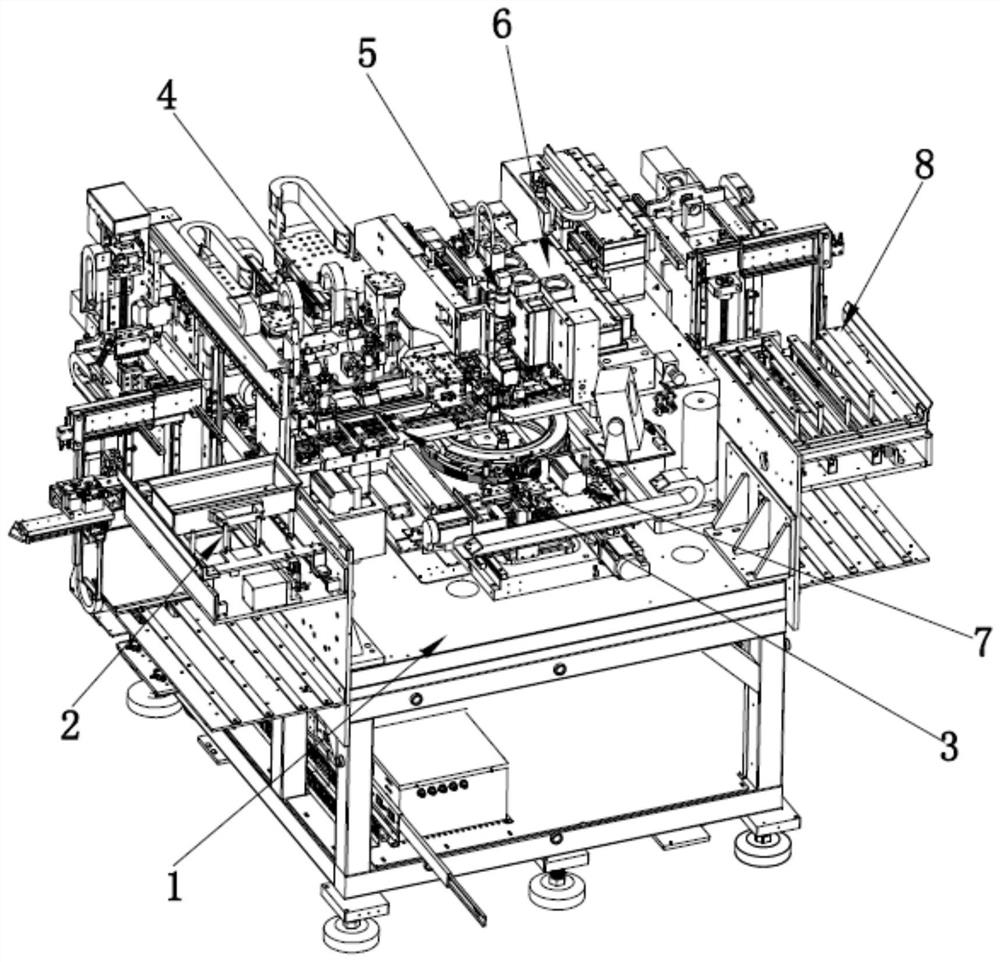
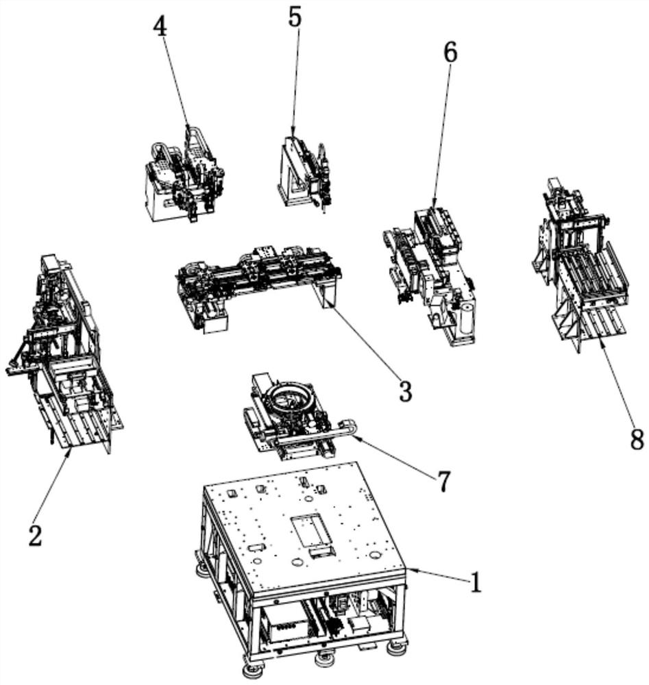
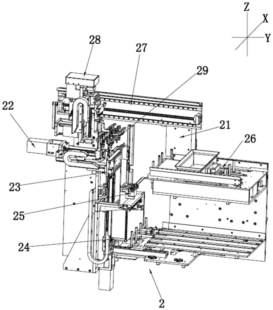
The invention provides a full-automatic planar IC die bonder and a die bonding method. The die bonder comprises a rack, a feeding mechanism and a receiving mechanism which are arranged at two ends ofthe rack respectively, a rail mechanism which is arranged between the feeding mechanism and the receiving mechanism; a dispensing mechanism, a lens mechanism and a welding head mechanism which are arranged on a side of the rail mechanism, and a film expanding and crystal ejecting mechanism which is arranged below the rail mechanism. The feeding mechanism is used for feeding an LED support to the rail mechanism, the rail mechanism is used for receiving and transferring the LED support, the dispensing mechanism is used for dispensing the LED support, and the film expanding and wafer jacking mechanism is used for jacking out a wafer on a blue film and fixing the wafer to the LED support under the cooperation of the lens mechanism and the welding head mechanism; the dispensing mechanism comprises a dispensing stand column fixed to the rack, a first dispensing assembly and a second dispensing assembly, wherein the first dispensing assembly and the second dispensing assembly are arranged onthe dispensing stand column. By arranging the two dispensing assemblies, the dispensing efficiency is greatly improved such that the die bonding efficiency is effectively ensured.

Description

technical field [0001] The application belongs to the technical field of automation equipment, and more specifically relates to a fully automatic planar IC crystal bonding machine and a crystal bonding method. Background technique [0002] At this stage, when LED chips are supplied to the die bonding machine, it is necessary to provide a blue film that pastes the LED chip on the film as a whole to make pieces. Generally, the blue film cannot be directly used for die bonding. It needs to be tightened, expanded and fixed. On the crystal ring or blue film carrier, and then clamped to the automatic film expansion crystal frame mechanism for positioning and calibration, it can be sucked by the suction nozzle on the crystal bonder to carry out the crystal bond operation. [0003] Before the existing die bonder fixes the LED chip, it needs to dispense glue on the LED bracket in advance, and then place the glued LED bracket on the die bonder to carry out the die bonding action. In o...

Claims


Application Information

Patent Timeline
Patent Type & Authority Patents(China)
IPC IPC(8): H01L33/52H01L33/62H01L33/48
CPCH01L33/48H01L33/52H01L33/62H01L2933/0033H01L2933/005H01L2933/0066
Inventor 胡新荣
Owner SHENZHEN XINYICHANG TECH CO LTD
Why Eureka
Try Eureka