Temperature regulating member

a technology of temperature regulation and member, which is applied in the direction of air heaters, indirect heat exchangers, light and heating apparatus, etc., can solve the problems of increased cost, increased labor, and difficulty in implementing temperature adjustment, so as to achieve greater ease of control, reduce labor intensity, and reduce labor intensity

Inactive Publication Date: 2008-02-07
HITACHI LTD
View PDF9 Cites 13 Cited by
  • Summary
  • Abstract
  • Description
  • Claims
  • Application Information

AI Technical Summary

Benefits of technology

[0012]Since a drive force using electricity, and so forth is not required by a method for controlling an ambient temperature by use of the heat-accumulating material provided with the stirrer, the transport vessel remains the same in size, and the temperature of the vessel as a whole can be controlled with greater ease while transportation can be simplified.
[0013]With the invention, it is possible to cause the churning flow to occur inside the heat-accumulating material during transportation. As a result, temperature inside the heat-accumulating material becomes uniform, so that it is possible to avoid a state where only the peripheral part of the heat-accumulating material is cooled early on to be subsequently solidified. Further, since a temperature difference from the ambient temperature is maintained, heat dissipation efficiency of the heat-accumulating material is kept at a high level. Furthermore, since the peripheral part of the heat-accumulating material is held in liquid state for a long duration, a buffer function thereof can be maintained for many hours.

Problems solved by technology

Further, since the peripheral part of the heat-accumulating material undergoes solidification early on, the buffer function as well will be lost.
Granting that the drive unit can be installed in the transport vessel for use in transportation of the cells, the transport vessel will increase in size in order to secure space necessary for installation of the drive unit, so that temperature adjustment will be difficult to implement, and the transport vessel itself will become heavier, and more expensive.
Furthermore, because an electrical drive unit will be inoperable in case that the battery runs down, or the electrical circuit is out of order, there is a possibility that it is difficult to guarantee reliable operation in the course of transportation over many hours.

Method used


Image

  • Temperature regulating member
  • Temperature regulating member
  • Temperature regulating member

Examples


Embodiment Construction

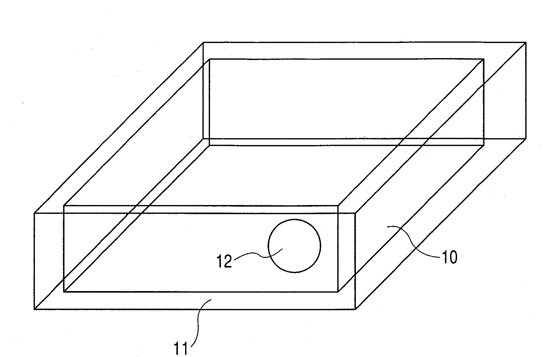
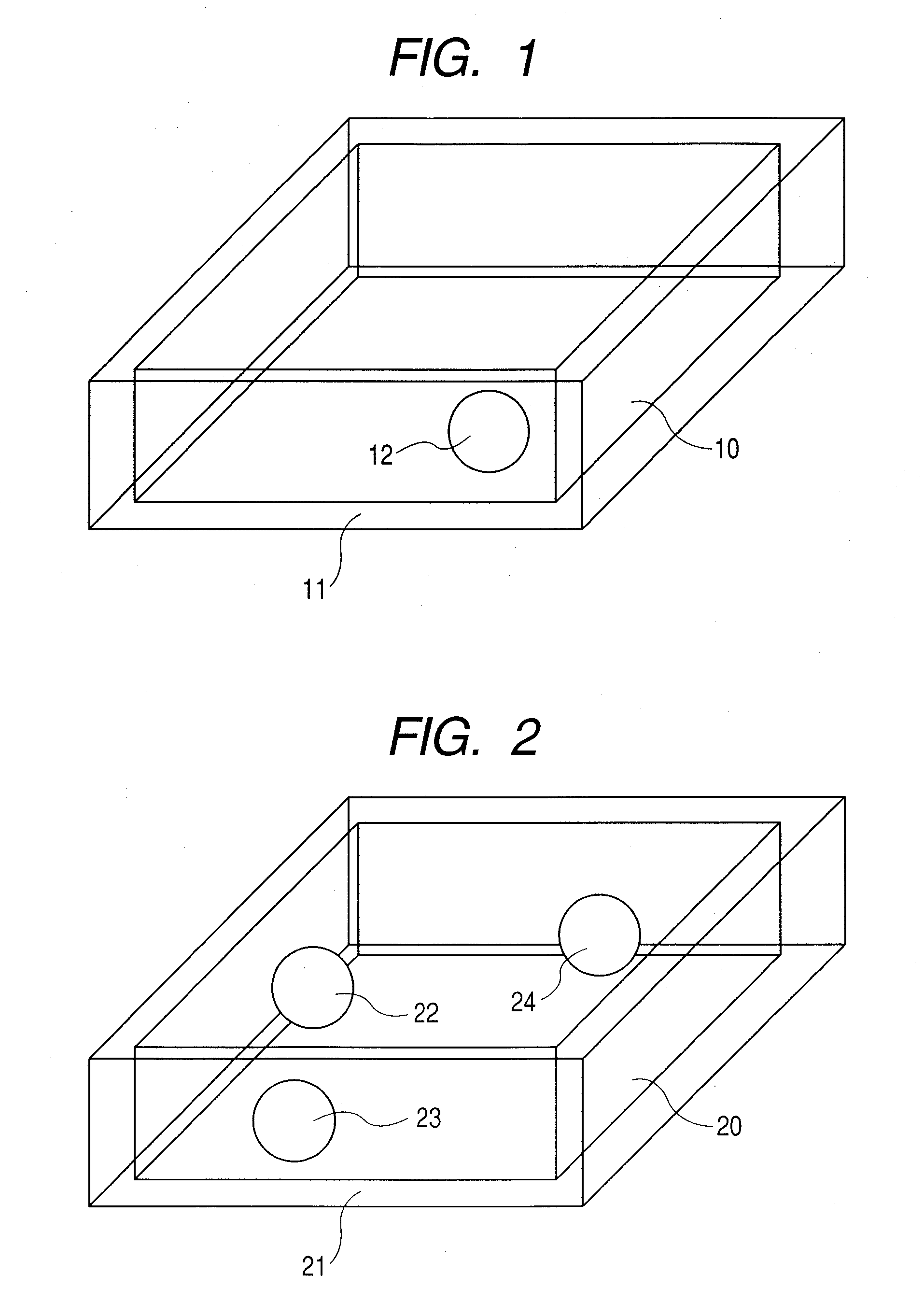
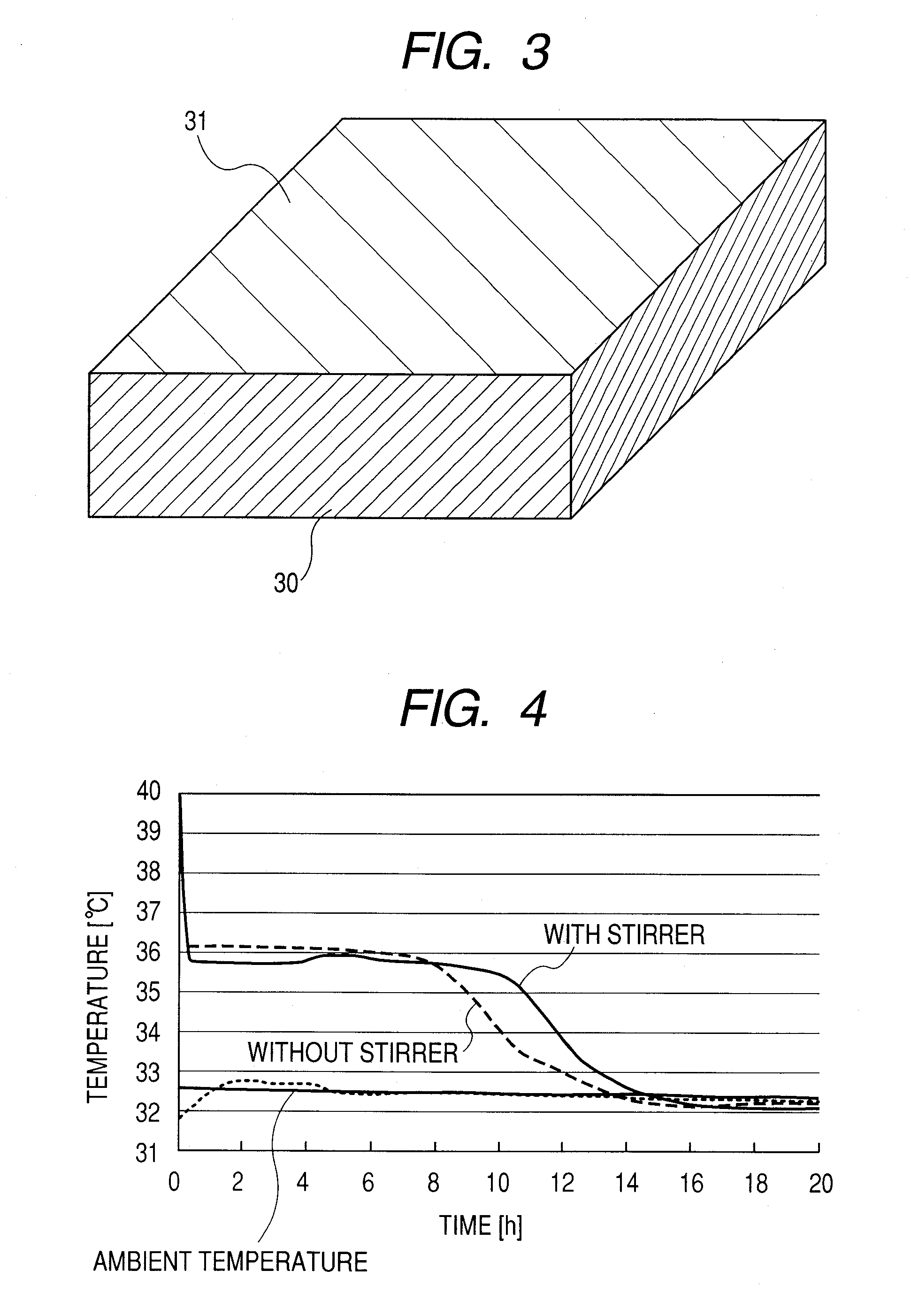
[0020]Embodiments of the invention will be described hereinafter with reference to the accompanying drawings. FIG. 1 is a perspective view showing an embodiment of a temperature regulating member according to the invention, comprising a heat-accumulating material, a stirrer disposed within the heat-accumulating material, and a vessel containing the heat-accumulating material, and the stirrer. FIG. 2 is a perspective view of another embodiment of a temperature regulating member according to the invention, comprising a heat-accumulating material, plural (3 pieces in this embodiment) stirrers disposed within the heat-accumulating material, and a vessel containing the heat-accumulating material, and the stirrers. FIG. 3 is a perspective view of still another embodiment of a temperature regulating member according to the invention, wherein parts of a vessel containing a heat-accumulating material, in contact with a culture vessel containing cells, are formed of a thermally conductive mem...


PUM


Abstract

A temperature regulating member capable of avoiding deterioration in heat dissipation efficiency of a heat-accumulating material, and deterioration in a buffer function thereof, due to ununiformity in heat distribution inside the heat-accumulating material. With the use of a churning flow occurring by disposing one piece of stirrer or plural stirrers inside the heat-accumulating material, and by causing a relative position of the stirrer, inside the heat-accumulating material, to be changed during transportation, it is possible to eliminate ununiformity in heat distribution inside the heat-accumulating material. The temperature regulating member has a feature in that a phenomenon of a peripheral part of the heat-accumulating material being first cooled to be subsequently solidified is avoided, thereby enabling the heat dissipation efficiency and the buffer function to be maintained.

Description

CLAIM OF PRIORITY[0001]The present application claims priority from Japanese application JP 2006-210462 filed on Aug. 2, 2006, the content of which is hereby incorporated by reference into this application.FIELD OF THE INVENTION[0002]The present invention relates to a temperature regulating member for use in the case of, for example, transporting cells or like, kept substantially at a predetermined temperature.BACKGROUND OF THE INVENTION[0003]In the case of a sample of cells or like, a change occurs to a load according to a temperature condition. Accordingly, temperature control is often required when transporting the sample of the cells or like. For example, there is a demand for transportation of cells kept at a temperature on the order of 36° C., higher than an ordinary outdoor air temperature, and close to a body temperature.[0004]Meanwhile, a method for managing temperature of a liquid phase substance includes, for example, a method whereby a stirrer rotatable by magnetism is p...

Claims


Application Information

Patent Timeline
Patent Type & Authority Applications(United States)
IPC IPC(8): F28D15/00
CPCC12M41/22Y02E60/145F28F13/125F28D20/02Y02E60/14
Inventor NOZAKI, TAKAYUKIKAN, KAZUTOSHI
Owner HITACHI LTD
Why Eureka
Try Eureka