
Discontinuously-perforated bridge frame

A bridge and bridge tube technology, applied in the field of bridges with intermittent holes, can solve the problems of easy deformation, high maintenance cost, low bridge rigidity, etc., and achieve the effects of strong bearing capacity, strong decorative function, and smooth and beautiful appearance.

Pending Publication Date: 2021-03-02
济南新材料产业技术研究院
View PDF3 Cites 0 Cited by
  • Summary
  • Abstract
  • Description
  • Claims
  • Application Information

AI Technical Summary

Problems solved by technology

[0008] Aiming at the problems existing in the above-mentioned prior art, the present invention provides a bridge frame with intermittent openings, which uses box girders with intermittent openings and small-sized cover plate components to form a box girder bridge frame with a circumferentially closed structure, which solves the problem of existing bridges. Low stiffness, easy deformation, high processing and maintenance costs

Method used


Image

  • Discontinuously-perforated bridge frame
  • Discontinuously-perforated bridge frame
  • Discontinuously-perforated bridge frame

Examples


Embodiment 1

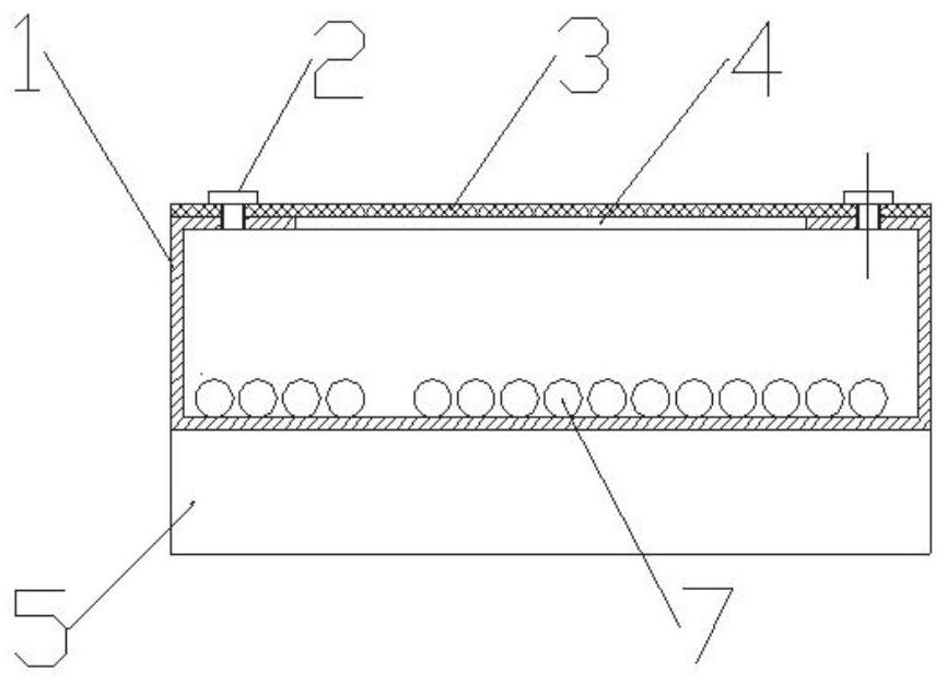
[0036] Such as Figure 1-3 As shown, a bridge frame with intermittent openings includes at least one set of bridge tubes 1, the surface of the bridge tubes 1 is open, and the surface of at least one set of openings has a cover plate assembly 3, and the cover plate assembly 3 is connected to the bridge frame through a connector 2. The pipe 1 is connected, and the cable 7 is located inside the bridge pipe 1.

[0037] The bridge tube 1 is a box-shaped structure, and can be made of metal materials such as steel plates, aluminum alloys, organic polymer materials such as polyvinyl chloride, or composite materials, and other materials. The polymer materials and their alloys are preferably selected to be produced by extrusion, and holes are opened on all circumferential surfaces of the bridge tube 1 after forming.

[0038] The opening can be used as a ventilation hole, and can also be used to pull and lay cables, bind and fix cables, check the condition of cables, and mark cable numb...


PUM


Abstract

The invention relates to a discontinuously-perforated bridge frame which comprises at least one group of bridge frame pipes, each bridge frame pipe is of a box beam structure with discontinuously-perforated surfaces, and cover plate assemblies are arranged on the surfaces of the at least one group of holes and connected with the bridge frame pipes through connecting pieces. The cover plate assembly is disassembled, laying, binding, fixing, detecting, marking and other operations can be carried out on the cable, the functions of the cover plate are achieved, the box beam and the cover plate assembly are connected and fixed, and the bridge body forms a closed and complete box beam structure. Rigidity is high, bearing capacity is high, the appearance is smooth, and the decoration function ishigh.

Description

technical field [0001] The invention relates to the technical field of power transmission and distribution and communication equipment, in particular to a bridge frame with intermittent openings. Background technique [0002] In factories or construction projects, cable trays are often used to lay cables. The basic functions of cable trays are support, protection and decoration. The existing cable tray system consists of a tray body, a tray bracket or hanger and its installation base. The bridge body forms a space for placing cables, and the cables are laid in the space formed by the bridge body and guided, supported, protected and decorated by the bridge body. [0003] The bridge body is usually placed on the support plane provided by the bridge bracket, support arm or hanger. The bridge body consists of a groove body and a cover plate to form a cable placement space. It is usually rectangular in cross-section with its long side lying flat on the support arm. The struc...

Claims


Application Information

Patent Timeline
IPC IPC(8): H02G3/04
CPCH02G3/0456
Inventor 马延春
Owner 济南新材料产业技术研究院
Learn More