Data transmission method and electronic equipment

A data transmission method and equipment technology, applied in the field of communication, can solve problems such as the inability to guarantee low latency of real-time video, and achieve the effect of low latency

Active Publication Date: 2021-03-02
LENOVO (BEIJING) LTD
View PDF8 Cites 4 Cited by
  • Summary
  • Abstract
  • Description
  • Claims
  • Application Information

AI Technical Summary

Problems solved by technology

However, since the use of the MPTCP protocol requires the support of the operating system and network protocol stack, and the use of the TCP protocol will bring a series of problems in the TCP protocol, it cannot guarantee low latency for applications such as real-time video

Method used


Image

  • Data transmission method and electronic equipment
  • Data transmission method and electronic equipment
  • Data transmission method and electronic equipment

Examples


Embodiment Construction

[0053] The following will clearly and completely describe the technical solutions in the embodiments of the application with reference to the drawings in the embodiments of the application. Apparently, the described embodiments are only some of the embodiments of the application, not all of them. Based on the embodiments in this application, all other embodiments obtained by persons of ordinary skill in the art without making creative efforts belong to the scope of protection of this application.

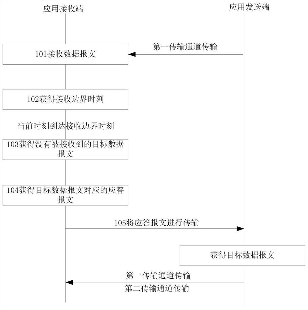
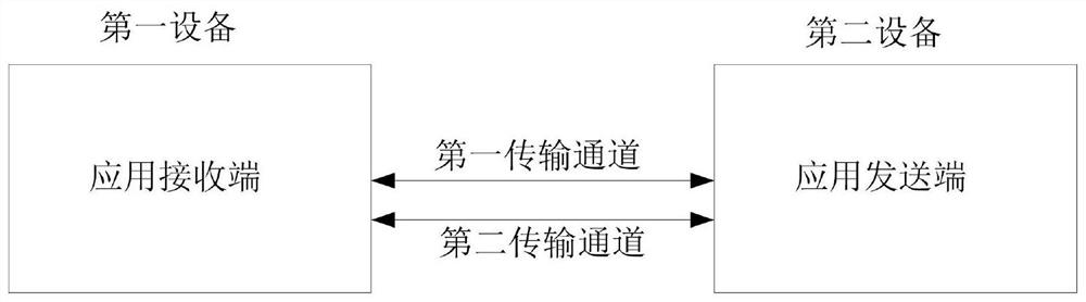
[0054] refer to figure 1 , is an implementation flowchart of a data transmission method provided in Embodiment 1 of the present application. This method can be applied to the application receiving end configured in the first device. The first device here can be understood as an electronic device that needs to receive data packets. Devices, correspondingly, electronic devices that need to send data messages can be recorded as second devices, such as figure 2 As shown in , the first...


PUM


Abstract

The invention discloses a data transmission method and electronic equipment, and the method is used for an application receiving end configured in first equipment, and comprises the steps: receiving adata message in a message set corresponding to a current message transmission period through a first transmission channel; obtaining a receiving boundary moment corresponding to the message transmission period reported by the first transmission channel at least according to the transmission delay parameter on the first transmission channel and the starting moment of the message transmission period, wherein the message transmission period is a period in which the application sending end configured in the second device sends the data message through the first transmission channel; when the current moment reaches the receiving boundary moment, obtaining a target data message which is not received by the application receiving end in the message set; obtaining a response message correspondingto the target data message; and at least transmitting the response message to the application sending end, so that the application sending end resends the target data message corresponding to the response message to the application receiving end through the first transmission channel and the second transmission channel at the same time.

Description

technical field [0001] The present application relates to the technical field of communications, and in particular to a data transmission method and electronic equipment. Background technique [0002] In many application scenarios of edge computing, it is necessary to establish a low-latency, large-bandwidth, and highly-reliable wireless transmission channel between the server and the terminal. For example, high-definition video upload, terminal posture in AR (Augmented Reality) applications, video and depth data upload, and cloud rendering video data delivery, etc. Existing implementations generally use Wi-Fi bearer, which has a high rate and guaranteed low delay, but the reliability of the Wi-Fi connection is not high, the delay fluctuates greatly, and the mobility is poor. For example, when the terminal roams between Wi-Fi connection points, There will be a 50-100ms interruption. [0003] In order to solve the problem of wifi transmission reliability, multi-channel tran...

Claims


Application Information

Patent Timeline
Patent Type & Authority Applications(China)
IPC IPC(8): H04L1/16H04L5/00H04L29/06
CPCH04L1/1607H04L1/1685H04L5/0055H04L69/16
Inventor 江森汪海明
Owner LENOVO (BEIJING) LTD
Why Eureka
Try Eureka