Check patentability & draft patents in minutes with Patsnap Eureka AI!

Rotary movement mechanism

A technology of moving mechanism and rotating shaft, which is applied in the direction of conveyor objects, transportation and packaging, loading/unloading, etc., can solve the problems of large footprint and inability to recover it, and achieve the effect of reducing the footprint

Active Publication Date: 2021-04-09
SUZHOU SHUANGQI AUTOMATION EQUIP CO LTD
View PDF15 Cites 0 Cited by
  • Summary
  • Abstract
  • Description
  • Claims
  • Application Information

AI Technical Summary

Problems solved by technology

At present, the conveyor line at the extended end of the telescopic machine cannot be retracted when it is not in use, and it occupies a large area

Method used


Image

  • Rotary movement mechanism
  • Rotary movement mechanism
  • Rotary movement mechanism

Examples


Embodiment Construction

[0018] The preferred embodiments of the present invention will be described in detail below in conjunction with the accompanying drawings, so that the advantages and features of the present invention can be more easily understood by those skilled in the art, so as to define the protection scope of the present invention more clearly.

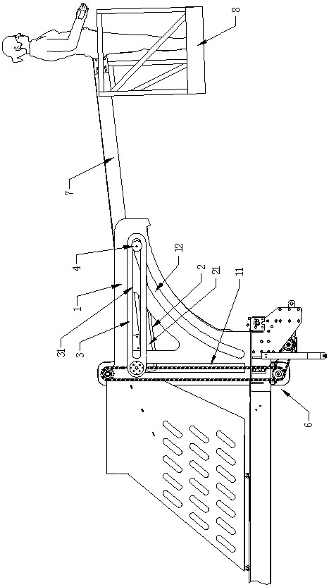
[0019] Such as Figure 1-4 As shown, a rotating and moving mechanism of this embodiment is provided between the side plates 1 on both sides, and the outer end of the conveying line 7 is provided with a station platform 8. The rotating and moving mechanism includes: a fixed plate 2, a fixed The plate 2 is fixedly arranged on one side of the conveying line 7, the fixed plate 2 is located on the inner side of the side plate 1, and the fixed plate 2 is provided with a fixing hole 21 extending along the length direction of the conveying line 7; the movable plate 3 is located on the side plate 1 side, specifically, the movable plate 3 in this embodimen...


PUM


Abstract

The invention relates to a rotating and moving mechanism, which is arranged between side plates on both sides, including a fixed plate, which is fixed on one side of the conveying line, and fixed holes are opened on the fixed plate; the movable plate, the movable plate Located on one side of the side plate and always set horizontally, the movable plate is provided with movable holes; the side plate is provided with vertical strip holes and obliquely curved arc holes; the connecting shaft passes through the movable holes, arc holes shaped hole and fixed hole, and can slide in the movable hole, arc-shaped hole and fixed hole; the inner end of the rotating shaft and the conveying line is connected to the side plates on both sides through the rotating shaft, and the end of the rotating shaft is fixedly provided with a slider. The block passes through the strip hole and can only slide up and down along the strip hole, the slide block is fixedly connected with the movable plate; the drive assembly is connected with the slide block and drives the slide block to slide up and down in the direction of the strip hole. The conveying line can be rotated and retracted to reduce the floor space.

Description

technical field [0001] The invention relates to a rotary movement mechanism. Background technique [0002] When the site uses the telescopic machine to unload the goods, it is necessary to use the telescopic machine to extend the station platform into the interior of the truck, and the operators stand on both sides of the telescopic machine to move the goods in the car or warehouse to the telescopic machine to realize unloading. At present, the conveying line at the extended end of the telescopic machine cannot be retracted when it is not in use, and the floor space is relatively large. Contents of the invention [0003] In order to overcome the above disadvantages, the object of the present invention is to provide a rotary movement mechanism that can rotate and retract the conveying line when not in use, and reduce the occupied area. [0004] In order to achieve the above purpose, the technical solution adopted by the present invention is: a rotary movement mechanism, th...

Claims


Application Information

Patent Timeline
Patent Type & Authority Patents(China)
IPC IPC(8): B65G67/24B65G41/00
CPCB65G41/002B65G67/24
Inventor 商积童
Owner SUZHOU SHUANGQI AUTOMATION EQUIP CO LTD
Features
  • R&D
  • Intellectual Property
  • Life Sciences
  • Materials
  • Tech Scout
  • Unparalleled Data Quality
  • Higher Quality Content
  • 60% Fewer Hallucinations
Learn More