Method for testing by using automobile clutch performance testing device

A test device and test method technology, applied in the direction of measuring device, vehicle test, fluid tightness test, etc., can solve the problems of poor control accuracy, inability to verify temperature resistance, and inaccurateness

Pending Publication Date: 2021-03-05
宜宾翼智新能源汽车科技有限公司
View PDF8 Cites 4 Cited by
  • Summary
  • Abstract
  • Description
  • Claims
  • Application Information

AI Technical Summary

Problems solved by technology

[0003] At present, in the field of automobile manufacturing, due to the inability to intervene in the performance test of the clutch system in the early design and development stage, the vehicle test can only be carried out after the prototype car is released, which increases the project cycle and the cost of design changes; Disassembly and assembly bring a lot of inconvenience, the test cycle is also long, and the seasonality is relatively large, so the clutch performance test caused by temperature difference cannot be carried out at any time
At present, the common clutch performance test devices on the market use cylinders and hydraulic cylinders as the driving source, which are not accurate enough, have poor control accuracy, and cannot be verified for temperature resistance, and the expansion of the equipment is not strong.
With the current shortening of the development cycle of automobile projects, launching better products to the market is to consider the comprehensive research and development capabilities of vehicle manufacturers. Therefore, the development cycle of vehicle models will become shorter and shorter. The limitations of vehicle testing, coupled with the continuous updating of models, will lead to more frequent matching of clutch systems, so there is an urgent need for efficient, reliable, and simple clutch performance test devices for pedal force, travel, reliability, and temperature resistance. And its corresponding test methods, so as to effectively guide the development of clutch performance

Method used


Image

  • Method for testing by using automobile clutch performance testing device
  • Method for testing by using automobile clutch performance testing device
  • Method for testing by using automobile clutch performance testing device

Examples


Embodiment Construction

[0036] Below with reference to the accompanying drawings, through the description of the embodiments, the specific embodiments of the present invention, such as the shape, structure, mutual position and connection relationship between the various parts, the role and working principle of the various parts, etc., will be further described. Detailed instructions:

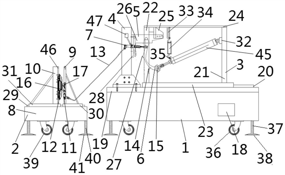
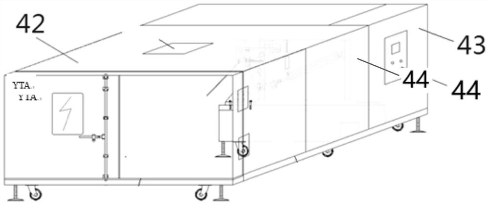
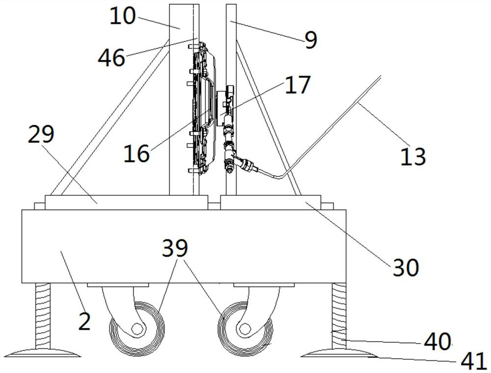
[0037] as attached figure 1 - attached image 3 As shown, the present invention is a kind of automobile clutch performance test device, and described automobile clutch performance test device comprises test device cabinet 1, separation execution bench 2, and test device cabinet 1 is provided with mounting bracket 3 and dash panel support 4, The clutch pedal 5 is connected with the dash panel bracket 4, one end of the telescopic cylinder 45 is flexibly connected with the installation bracket 3, the other end of the telescopic cylinder 45 is connected with the pedal tread 6 of the clutch pedal 5, and the clutch pedal 5 ...


PUM


Abstract

The invention provides a method for testing by using an automobile clutch performance test device. The method comprises a clutch pedal characteristic test method, wherein the test steps of the clutchpedal characteristic test method are that a displacement sensor I (14), a force sensor I (15), a force sensor II (16) and a displacement sensor II (17) are respectively installed in place; an automobile clutch performance test device is started, a telescopic air cylinder (45) stretches out and then retracts within a set time, a clutch pedal (5) is controlled to complete a complete clutch pedal action, and the displacement sensor I (14), the force sensor I (15), the force sensor II (16) and the displacement sensor II (17) feed data back to a control component (18) respectively. According to theinvention, the state of a whole automobile clutch system can be accurately simulated, the automobile clutch performance can be tested all the year round, reliable data support is provided for productdevelopment and innovative design, and the product quality is effectively improved.

Description

technical field [0001] The invention belongs to the technical field of auto parts testing, and in particular relates to a test method using an auto clutch performance testing device. Background technique [0002] The performance of clutch characteristics of the whole vehicle mainly refers to the driver's operating perception when manipulating the clutch pedal. In all MT-type vehicles, the clutch operation cannot be avoided. It is necessary for the driver to step on the pedal to separate the driven disc of the clutch from the flywheel of the engine. And combined, the power can be cut off and input to ensure the normal start of the vehicle and smooth shifting. The clutch pedal force felt by the driver's left foot is mainly the maximum pedal force of the clutch system. Its source comes from the separation force of the working point of the clutch driven disc. When the system efficiency is converted to the clutch pedal, the clutch pedal force of the car is usually required to be...

Claims


Application Information

Patent Timeline
Patent Type & Authority Applications(China)
IPC IPC(8): G01M17/007G01M13/022G01M13/027G01M3/00
CPCG01M17/007G01M13/022G01M13/027G01M3/00
Inventor 丁勇邹凌华刘振华
Owner 宜宾翼智新能源汽车科技有限公司
Why Eureka
Try Eureka