A multifunctional integrated installation box for inductors

A technology for inductors and installation boxes, which is applied in the direction of transformer/reactor installation/support/suspension, transformer/inductor shell, transformer/inductor parts, etc., and can solve the influence of inductor integrated installation box electronic components and circuits, Affect the working quality and service life of electronic devices, increase the labor intensity of workers and other issues, achieve the effect of improving dust removal efficiency, saving long-term use costs, strengthening practicability and market competitiveness

Active Publication Date: 2022-01-18
山东瑞科成套电气有限公司
View PDF10 Cites 0 Cited by
  • Summary
  • Abstract
  • Description
  • Claims
  • Application Information

AI Technical Summary

Problems solved by technology

[0002] Inductor integrated installation box is a commonly used device in power equipment. Inductor integrated installation box generally contains more inductor components and circuits. During the operation of inductor integrated installation box, these electronic components and circuits are energized After that, a large amount of dust is gradually absorbed and deposited, which makes the electronic components and circuits in the inductor integrated installation box extremely vulnerable. A large amount of dust will seriously affect the working quality and service life of electronic devices
[0003] In order to solve the above technical problems, those skilled in the art generally perform regular manual unpacking and cleaning during the use of the inductor integrated installation box to remove the dust accumulated in the inductor integrated installation box; however, this regular unpacking and cleaning It is also very troublesome and greatly increases the labor intensity of workers.

Method used


Image

  • A multifunctional integrated installation box for inductors
  • A multifunctional integrated installation box for inductors
  • A multifunctional integrated installation box for inductors

Examples


Embodiment Construction

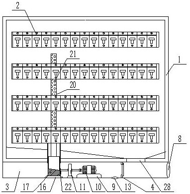
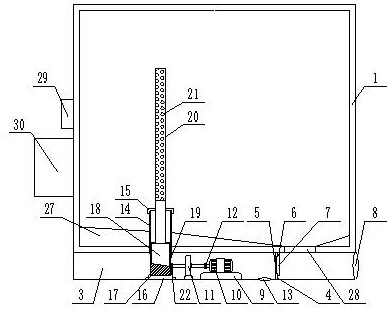
[0030] The present invention is specifically described below in conjunction with accompanying drawing, as Figure 1-5 shown;

[0031] The invention of the present application lies in that the dust removal chamber 3 is fixedly installed on the lower surface of the installation box, the dust removal chamber is a long strip box with a rectangular longitudinal section, and a partition 4 is fixedly installed in the dust removal chamber. The partition divides the inner cavity of the entire installation cavity into left and right parts, the partition is provided with ventilation holes 5, and a door is installed on the right side of the partition, and the door is turned over to the right side of the partition Open, the door includes a rotating shaft 6 fixedly installed above the ventilation hole, a baffle 7 is installed on the rotating shaft, the baffle blocks the ventilation hole, the baffle turns upwards around the rotating shaft, and the right side of the dust removal chamber A di...


PUM


Abstract

The invention discloses a multifunctional integrated installation box for inductors, which includes an installation box body, and a plurality of inductor installation plates are arranged in the installation box, and inductors and matching wires are installed on the inductor installation plates. A dust removal chamber is fixedly installed on the lower surface of the installation box. The dust removal chamber is a long strip box with a rectangular longitudinal section. A partition is fixedly installed in the dust removal chamber, and the partition divides the inner cavity of the entire installation chamber. Divided into left and right parts, the partition is provided with a ventilation hole, a door is installed on the right side of the partition, and the door is turned and opened to the right side of the partition, and the door is fixedly installed on the The rotating shaft above the ventilation hole, the baffle plate is installed on the rotating shaft, the baffle plate covers the ventilation hole, the baffle plate turns upwards around the rotating shaft, a discharge port is arranged on the right side of the dust removal chamber, and the dust removal chamber The motor mounting seat is fixedly installed inside, and the motor mounting seat is located on the left side of the partition. The beneficial effect of the invention is that it has multiple dust removal functions, reasonable structure design and strong practicability.

Description

technical field [0001] The invention relates to the technical field of integrated installation of power inductors, in particular to a multifunctional integrated installation box for inductors. Background technique [0002] Inductor integrated installation box is a relatively commonly used device in power equipment. Inductor integrated installation box generally contains more inductor components and circuits. During the operation of inductor integrated installation box, these electronic components and circuits are energized Afterwards, a large amount of dust is gradually absorbed and deposited, which leads to the extremely susceptible electronic components and circuits in the inductor integrated installation box. A large amount of dust will seriously affect the working quality and service life of electronic devices. [0003] In order to solve the above technical problems, those skilled in the art generally perform regular manual unpacking and cleaning to remove the dust accum...

Claims


Application Information

Patent Timeline
Patent Type & Authority Patents(China)
IPC IPC(8): H01F27/02H01F27/06H01F27/40B08B5/02B08B7/02
CPCH01F27/022H01F27/06H01F27/40B08B5/02B08B7/02
Inventor 赵辉郭红霞
Owner 山东瑞科成套电气有限公司
Why Eureka
Try Eureka