
Nano-ridge engineering

A nano-chamber technology, applied in the field of III-V semiconductors, can solve problems such as uneven formation and problems, and achieve the effect of reducing defect density

Pending Publication Date: 2021-03-05
INTERUNIVERSITAIR MICRO ELECTRONICS CENT (IMEC VZW)
View PDF0 Cites 0 Cited by
  • Summary
  • Abstract
  • Description
  • Claims
  • Application Information

AI Technical Summary

Problems solved by technology

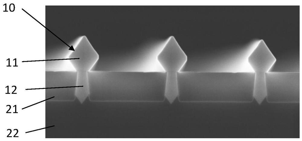
However, the remaining strain field (typically III / V heteroepitaxy on Si) leads to non-uniform formation of InGaAs nanoridges with rough top surfaces, which is problematic for arbitrary device integration.

Method used


Image

  • Nano-ridge engineering
  • Nano-ridge engineering
  • Nano-ridge engineering

Examples


Embodiment Construction

[0039] The present invention will be described with respect to specific embodiments and with reference to certain drawings but the invention is not limited thereto but only by the claims. The drawings described are illustrative only and non-limiting. In the drawings, the size of some of the elements may be exaggerated and not drawn on scale for illustrative purposes. The dimensions and relative dimensions do not correspond to actual reductions in the practice of the invention.

[0040] Furthermore, in the description and claims, the terms top, bottom, etc. are used for descriptive purposes and not necessarily for describing relative positions. It is to be understood that the terms so used are interchangeable under appropriate circumstances and that the described embodiments of the invention are capable of operation in other orientations than described or illustrated herein.

[0041] It should be noted that the term "comprising", used in the claims, should not be interpreted ...


PUM

PropertyMeasurementUnit
thicknessaaaaaaaaaa

Abstract

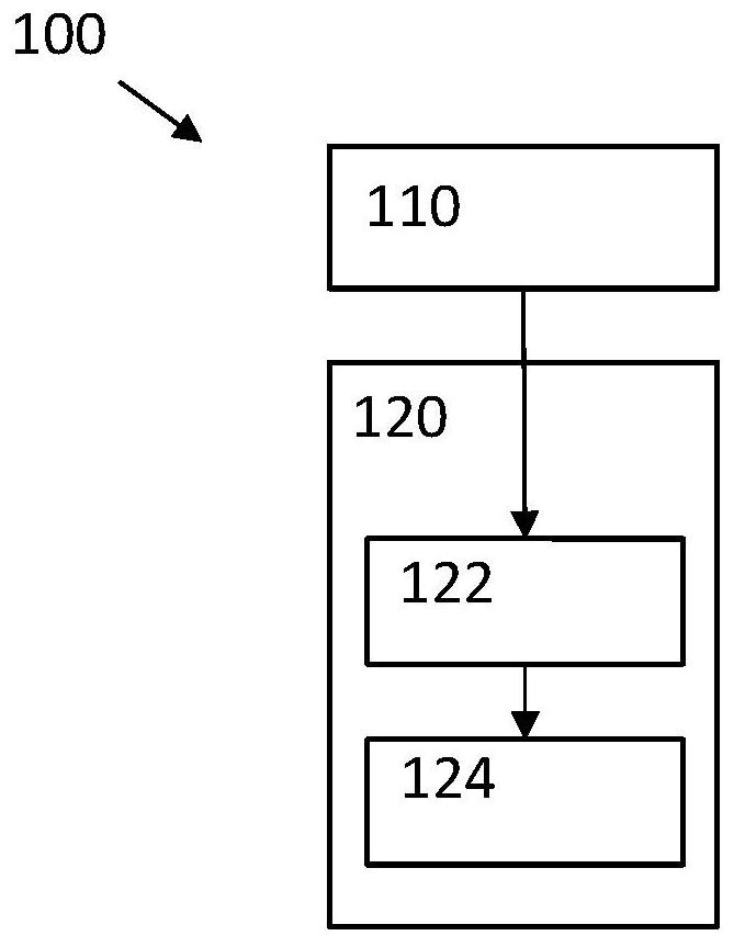
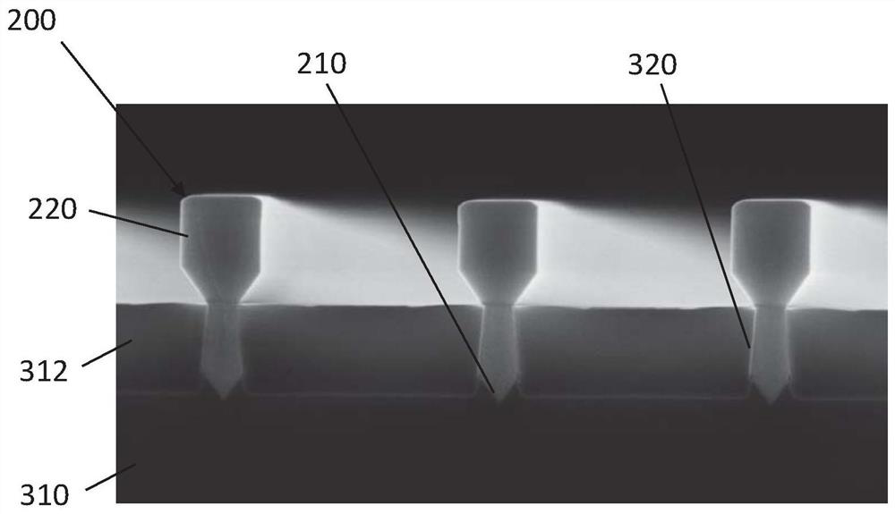
A method (100) for growing at least one III / V nano-ridge (200) on a silicon substrate (310) in a chamber. The method comprises: patterning (110) an area on a silicon substrate (310) thereby forming atrench (320) on the silicon substrate; growing (120) the III / V nano-ridge (200) by initiating growth (122) of the III / V nano-ridge (200) in the trench (320), thereby forming and filling layer(210) ofthe nano-ridge inside the trench, and by continuing growth (124) out of the trench (320) on top of the filling layer (210), thereby forming a top part (220) of the nano-ridge (200), wherein at least one surfactant is added in the chamber when the nano-ridge is growing out of the trench.

Description

technical field [0001] The present invention relates to the field of III-V semiconductors. More specifically, it relates to methods for the monolithic integration of III-V devices on silicon substrates. Background technique [0002] III-V devices are difficult to monolithically integrate on silicon substrates because of the lattice mismatch between III-V materials and silicon substrates, resulting in defects in III-V materials. To overcome these difficulties, nanoridges are grown in narrow trenches. [0003] Nanoridges made of III / V materials are now used in very different integration approaches. For example, these nano-ridges are InGaAs nano-ridges (with different In contents) grown on patterned silicon substrates. The patterned substrate can be obtained by isolating the process flow with shallow trenches. Nano-ridges are obtained by trench filling and growth. Successful device integration on these nanoridges requires colinear and uniform growth of nanoridges on a patt...

Claims


Application Information

Patent Timeline
Patent Type & Authority Applications(China)
IPC IPC(8): H01L21/02
CPCH01L21/02381H01L21/0243H01L21/02538H01L21/02546H01L21/0259H01L21/0262C30B29/42C30B29/40C30B25/00C30B25/04C30B29/60C30B25/105C30B25/18H01L21/76224H01L21/76877
Inventor B·库纳特R·兰格Y·莫里斯M·巴士尼科娃
Owner INTERUNIVERSITAIR MICRO ELECTRONICS CENT (IMEC VZW)
Learn More