Binding method of intelligent binding machine
A strapping machine and intelligent technology, applied in the field of strapping, can solve the problems of unsatisfactory bundling of objects to be bundled, narrow application range, and low transmission efficiency, and achieve the effect of convenient and fast cutting process, wide application range of strapping, and reduced labor intensity
- Summary
- Abstract
- Description
- Claims
- Application Information
AI Technical Summary
Problems solved by technology
Method used
Image
Examples
Embodiment 1
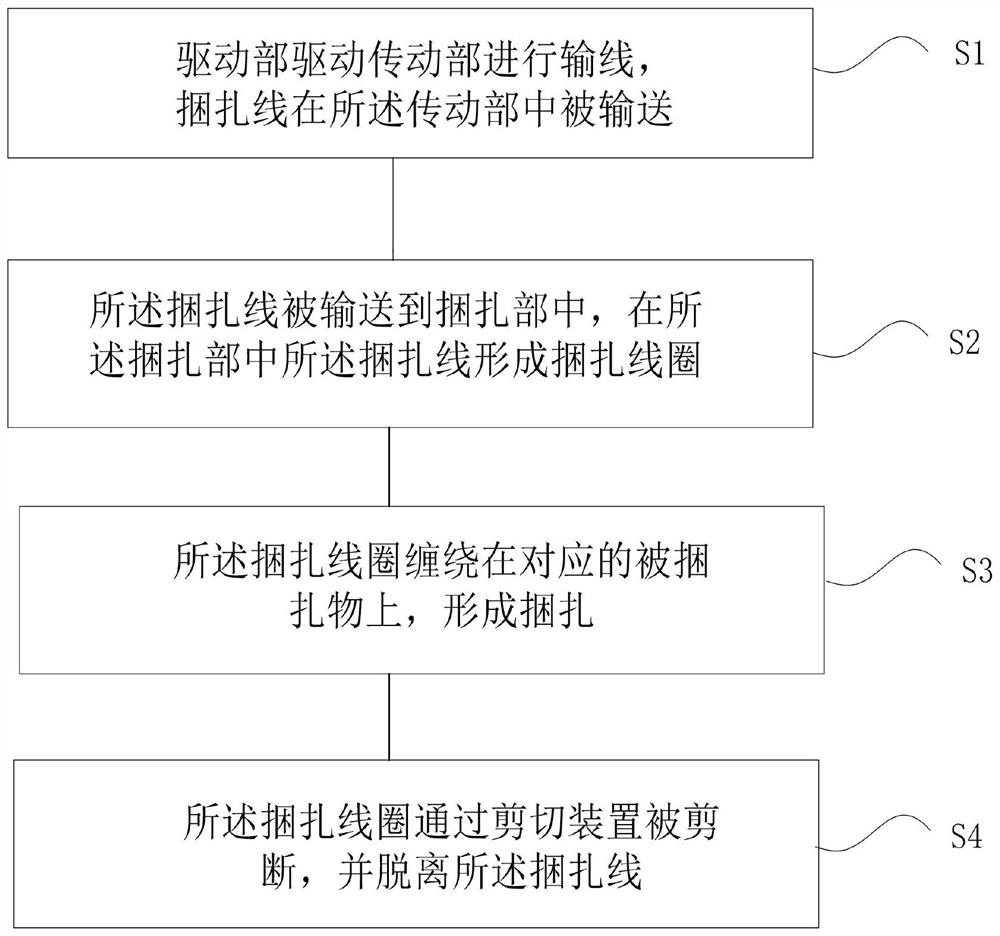
[0046] see figure 1 , a method for bundling with an intelligent strapping machine, comprising:
[0047] S1: The driving part drives the transmission part to carry out wire transmission, and the binding wire is conveyed in the transmission part;
[0048] S2: the binding wire is conveyed into the binding part, and the binding wire forms a binding coil in the binding part;
[0049] S3: The binding coil is wound on the corresponding object to be bound to form a binding;
[0050] S4: The binding coil is cut by the cutting device and separated from the binding wire.
[0051] The intelligent binding control method provided in this embodiment realizes fast and convenient binding of plants and vines, and has high binding efficiency.
Embodiment 2
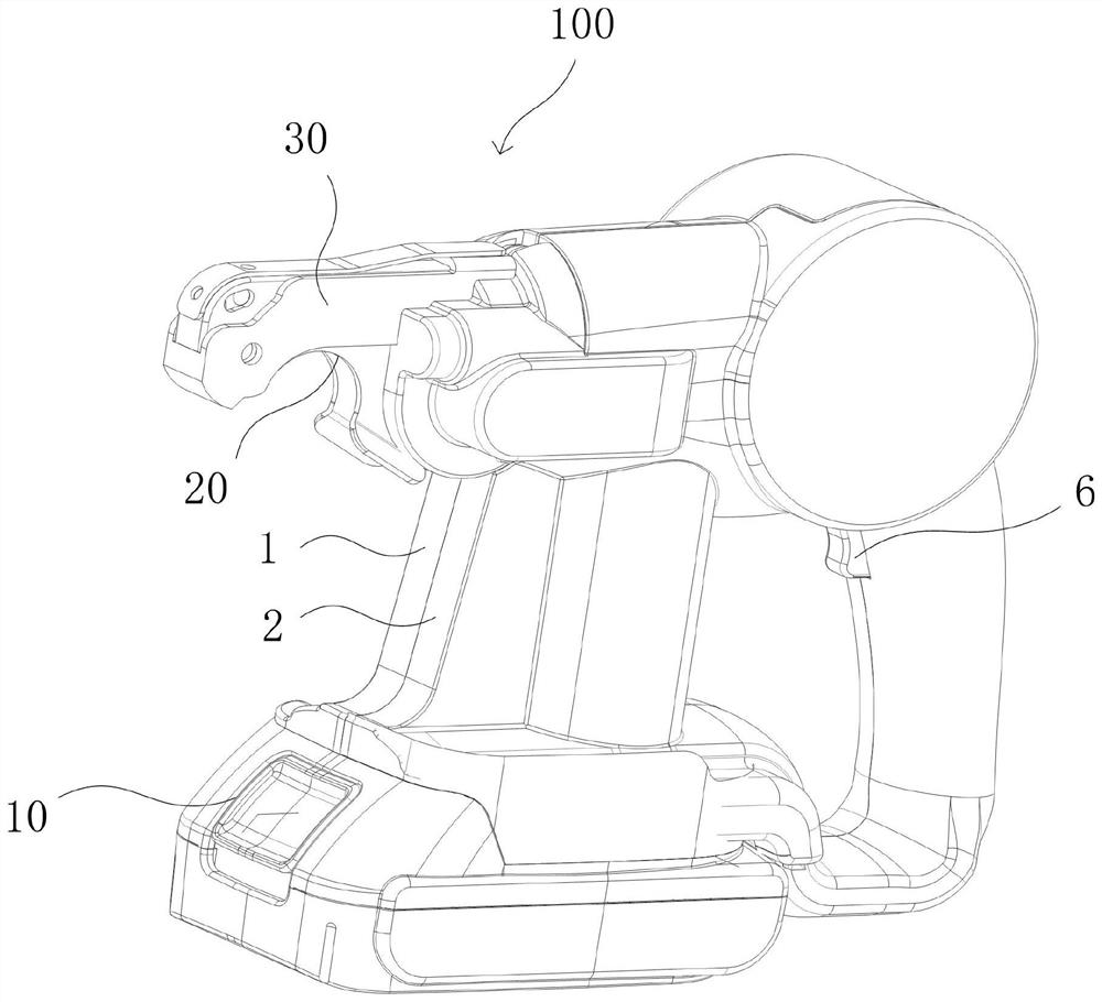
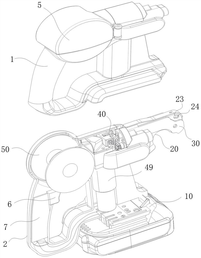
[0053] see figure 2 and image 3 , the transmission part 40 in step S1 is driven by the driving part 49, and the binding wire is driven by the transmission part 40 to move to the binding part 20; ; The shearing device 30 in step 4 is connected in transmission with the transmission part 40, and the binding coil is cut off from the binding line by the shearing device 30. The binding part can quickly bind the plants and vines, and the set binding part can change the conveying path of the binding wire, so that the binding wire used for binding can be automatically wound around the surface of the vines in the form of a ring to realize binding; greatly improved The binding efficiency reduces the labor intensity of people; the shearing device provided can quickly cut the binding line, which improves the work efficiency and avoids the traditional process of artificially cutting with scissors or other sharp blades.
[0054] see Figure 4 , the driving part 49 can drive the transmis...
Embodiment 3
[0062] see Figure 5 and Image 6 , the shearing device 30 in step S4 includes a shearing power part (not shown in the figure), and the shearing power part is used to provide shearing power for shearing the binding coil. The shearing power part includes a worm 65 , and the worm 65 is in transmission connection with the second driven wheel 63 through the third driven wheel 62 . It is convenient for the secondary rotation of the driven wheel to drive the rotation of the worm, so as to realize the transmission of force.
[0063] Further, the shearing device includes a shearing knife 32 and a shearing transmission part 60, the shearing transmission part includes a transmission housing 33, a shearing power part and a cam 67, and the shearing power part is driven by the shearing transmission part 60 to drive the cam 67 to rotate , thereby driving the transmission housing 33 to move upwards, and then driving the shearing knife 32 to trim the thread. The cam is driven by the sheari...
PUM
 Abstract
Description
Claims
Application Information
 - R&D
- Intellectual Property
- Life Sciences
- Materials
- Tech Scout
- Unparalleled Data Quality
- Higher Quality Content
- 60% Fewer Hallucinations
Browse by: Latest US Patents, China's latest patents, Technical Efficacy Thesaurus, Application Domain, Technology Topic, Popular Technical Reports.
© 2025 PatSnap. All rights reserved.Legal|Privacy policy|Modern Slavery Act Transparency Statement|Sitemap|About US| Contact US: help@patsnap.com


