
End head assembly for endoscope

A technology of head components and endoscopes, applied in the field of endoscopes, can solve the problem of space occupied by head components and reduce the risk of fracture

Pending Publication Date: 2021-03-09
安布股份有限公司
View PDF0 Cites 0 Cited by
  • Summary
  • Abstract
  • Description
  • Claims
  • Application Information

AI Technical Summary

Problems solved by technology

Providing a small tip assembly can be especially challenging where the endoscope includes both a camera and a working channel extending through the tip assembly because the camera and working channel are positioned one above the other within the tip assembly, This takes up space in the radial direction of the tip assembly

Method used


Image

  • End head assembly for endoscope
  • End head assembly for endoscope
  • End head assembly for endoscope

Examples


Embodiment Construction

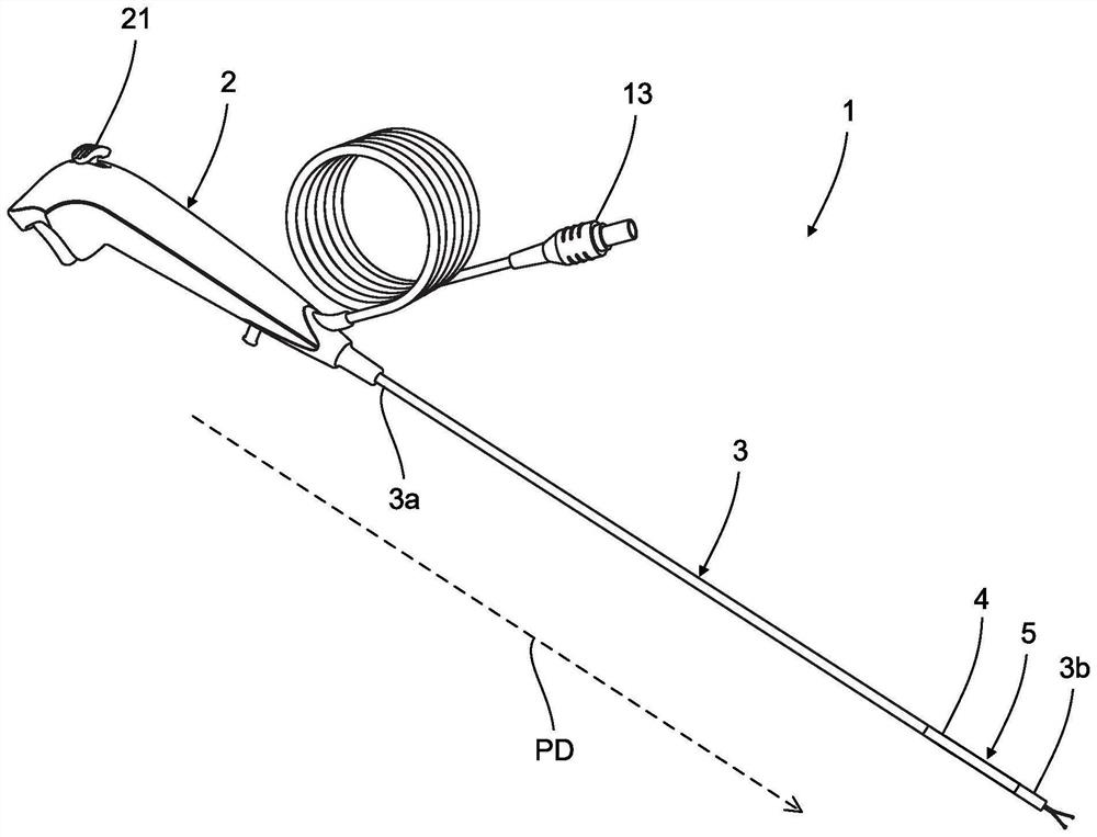
[0156] first reference Figure 1a , shows an endoscope 1 . Endoscopes are disposable and are not intended to be cleaned and reused. The endoscope 1 includes an elongated insertion tube 3 . An operating handle 2 is arranged at the proximal end 3 a of the insertion tube 3 . The operating handle 2 has a control lever 21 for actuating the tip assembly 5 at the distal end 3 b of the insertion tube 3 via a control wire. A camera assembly 6 is positioned in the tip head 5 and is configured to transmit image signals to a monitor 11 via a monitor cable 13 of the endoscope 1 .

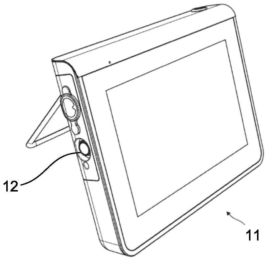
[0157] exist Figure 1b In , a monitor 11 is shown. Monitor 11 may allow an operator to view images captured by camera assembly 6 of endoscope 1 . The monitor 11 comprises a cable socket 12 to which a monitor cable 13 of the endoscope 1 can be connected to establish signal communication between the camera assembly 6 of the endoscope 1 and the monitor 11 .

[0158] The direction PD from proximal to distal i...


PUM


Abstract

Provided is an end head assembly for an endoscope. The end head assembly has a proximal end for connection to other portions of the endoscope and a distal end positioned opposite the proximal end, thedistal end for forming the distal end of the endoscope. The end head assembly comprises: a working channel extending in a longitudinal direction extending from the proximal end of the end head assembly towards the distal end, and a camera assembly including a flexible printed circuit and a camera module, the camera module including an image sensor and a lens group and extending in a longitudinaldirection, the camera module including a proximal connection surface, where the camera module is positioned above the working channel in an up-down direction such that a lateral direction extends transverse to both the camera module and the working channel, wherein the flexible printed circuit extends from a connection with a connection surface of the camera module in a lateral direction beyond the connection surface, forming a first bent portion of the flexible printed circuit toward a proximal end of the end head assembly, and wherein the first bent portion of the flexible printed circuit isarranged proximal to the connection surface of the camera module.

Description

technical field [0001] The present disclosure relates to endoscopes, and more particularly, to a tip assembly for an endoscope. Background technique [0002] Endoscopes are well known for visual inspection of hard-to-reach locations such as body cavities of the human body. Typically, an endoscope includes an elongated insertion tube with a handle at its proximal end (from the operator's point of view) and a device such as a built-in camera at its distal end. Visually inspect the device. The definitions of the terms "distal" and "proximal" as used herein for endoscopes in general are adhered to in this specification, ie proximal is the end closest to the operator and distal is the end farthest from the operator. [0003] As the name suggests, endoscopes are used to look inside the body, such as a patient's lungs or other body cavities. Therefore, modern endoscopes are usually equipped with a light source and visual receptors, including visual sensors such as cameras or ima...

Claims


Application Information

Patent Timeline
Patent Type & Authority Applications(China)
IPC IPC(8): A61B1/00A61B1/005A61B1/008A61B1/012A61B1/05A61B1/06A61B1/07A61B1/307
CPCA61B1/00112A61B1/0052A61B1/0055A61B1/0057A61B1/008A61B1/05A61B1/07A61B1/0684A61B1/012A61B1/307A61B1/00096A61B1/051H05K2201/056A61B1/0011A61B1/018A61B1/00188A61B1/015A61B1/0676H04N23/555
Inventor 莫滕·斯伦森
Owner 安布股份有限公司
Learn More