
Precision filter for chemical production and processing

A precision filter and chemical production technology, applied in the direction of fixed filter elements, filter separation, chemical instruments and methods, etc., can solve the problems of low filtration efficiency, high cost, complex structure, etc., and achieve simple structure and low cost Effect

Inactive Publication Date: 2021-03-09
陆杰
View PDF16 Cites 0 Cited by
  • Summary
  • Abstract
  • Description
  • Claims
  • Application Information

AI Technical Summary

Problems solved by technology

[0002] Precision filters are common in the chemical industry, such as crude oil filtration, chemical mixture filtration, etc. Its core component is a corrosion-resistant stainless steel sintered filter cartridge, and the filtration accuracy reaches the micron level. , block the filter cartridge and the original liquid during cleaning, and then connect the sewage pipe, backwash the inner cavity of the filter cartridge, and the impurities are discharged through the sewage pipe; the advantage of this kind of precision filter is that it is convenient for cleaning and maintenance of the filter cartridge; but there are still some defects: 1. The filter cartridge cannot be filtered normally during backwashing, and the filtration pressure gradually increases during use, and the filtration efficiency is low. Specifically, it is impossible to realize real-time cleaning during the working process to stabilize the filtration pressure; 3. In order to solve the situation that the cleaning filter cartridge cannot be cleaned in the normal production process, multiple filter cartridges are now used to rotate and filter, which is costly and complicated in structure

Method used


Image

  • Precision filter for chemical production and processing
  • Precision filter for chemical production and processing
  • Precision filter for chemical production and processing

Examples


Embodiment 1

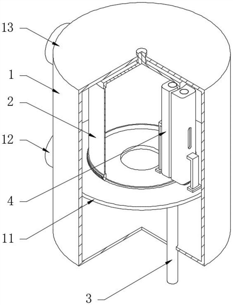
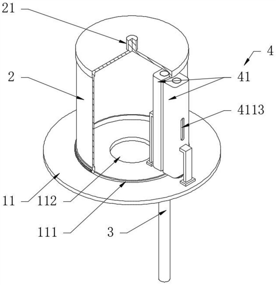
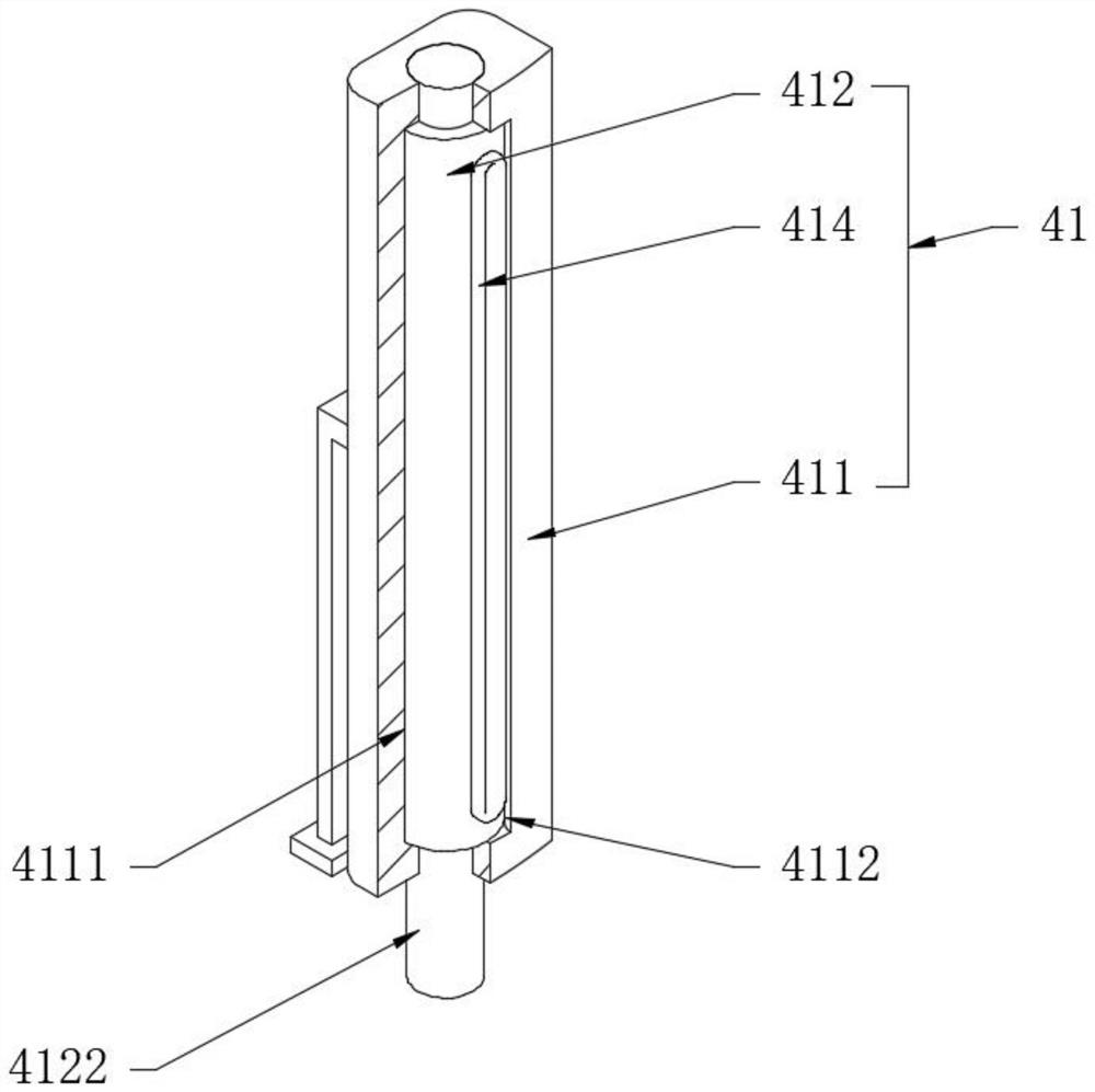
[0031] see Figure 1-6 , a precision filter for chemical production and processing, including an outer cylinder 1, a filter cartridge 2 and a sewage pipe 3, the filter cartridge 2 is arranged in the outer cylinder 1, the top of the filter cartridge 2 is a blind end and the bottom is an open end, the filter cartridge The top of the filter cartridge 2 is fixedly provided with a drive shaft 21 that is rotatably connected to the top of the outer cylinder 1, and the outer cylinder 1 is fixedly provided with a partition plate 11 that is rotatably matched with the bottom of the filter cartridge 2, and the partition plate 11 divides the inner cavity of the outer cylinder 1 into a raw liquid chamber And the clean chamber, specifically, the upper end surface of the partition plate 11 is provided with an annular groove 111 that is rotatably connected to the bottom of the filter cartridge 2, and the outside of the outer cylinder 1 is fixedly provided with a feed pipe 12 and a discharge pip...

Embodiment 2

[0033] see Figure 5The difference from Embodiment 1 is that the sewage guiding combination 41 also includes a gear one 415 and a gear two 416. The gear one 415 is located under the partition plate 11 and is respectively fixedly sleeved on two transmission shafts 4122. The two gears one 415 Engagement, the second gear 416 is located above the partition plate 11 and is fixedly sleeved on the transmission shaft 4122 located outside the filter cartridge 2. The second gear 416 meshes with the outer wall of the filter cartridge 2 and is close to the bottom, so that the filter cartridge 2 rotates It can drive the second gear 416 to rotate, and the second gear 416 drives the other transmission shaft 4122 to rotate through the transition connection of the two first gears 415 to realize the synchronous operation of the two rotary columns 412. The structure is simple and the cost is low.

Embodiment 3

[0035] see figure 2 and Figure 5 The difference from Example 1 is that the other side of the fixed cuboid 411 outside the filter cartridge 2 is provided with a feed hole 4113, and the bottom of the corresponding transmission shaft 4122 at the bottom of the fixed cuboid 411 is screwed with a plug 5, and the feed hole 4113 is located in the clean chamber, and the plug 5 seals the transmission shaft 4122, thus no need to connect the external air supply pipeline. Due to the certain pressure in the clean chamber, a small amount of clean liquid is in the two waist-shaped holes inside and outside the filter cartridge 2 When 4121 is connected, it passes through the filter cartridge 2 through the feed hole 4113, then enters the waist-shaped hole 4121 located in the filter cartridge 2, and then is discharged through the sewage pipe 3. During this process, the impurities and dirt on the inner wall of the filter cartridge 2 are removed. Clean liquid reverse osmosis mixes and separates ...


PUM


Abstract

The invention discloses a precision filter for chemical production and processing, which comprises an outer cylinder, a filtering cylinder and a blow-off pipe, wherein the filtering cylinder is arranged in the outer cylinder, the top of the filtering cylinder is a blind end, the bottom of the filtering cylinder is an open end, and a driving shaft rotationally connected with the top of the outer cylinder is fixedly arranged at the top of the filtering cylinder; and a separation disc rotationally matched with the bottom of the filtering cylinder is fixedly arranged in the outer cylinder. In theinvention, the bottom of the filtering cylinder is open, a separation disc rotatably matched with the bottom of the filtering cylinder is arranged in the outer cylinder, the separation disc is provided with a sewage guide part, the sewage guide part comprises two sewage guide combinations positioned inside and outside the surface wall of the filtering cylinder, the two sewage guide combinations can be circularly communicated and blocked, and external high-pressure air enters the sewage guide combination positioned outside the filtering cylinder during communication; and impurities and dirt onthe inner surface wall of the filtering cylinder can be blown away from the filtering cylinder and then discharged through a blow-off pipe, the two sewage guide combinations can be connected and disconnected at different positions on the filtering cylinder through rotation of the filtering cylinder, and then blockage removing and blocking preventing treatment can be achieved in the normal operation process.

Description

technical field [0001] The invention relates to the technical field of chemical filtration, in particular to a precision filter for chemical production and processing. Background technique [0002] Precision filters are common in the chemical industry, such as crude oil filtration, chemical mixture filtration, etc. Its core component is a corrosion-resistant stainless steel sintered filter cartridge, and the filtration accuracy reaches the micron level. , block the filter cartridge and the original liquid during cleaning, and then connect the sewage pipe, backwash the inner cavity of the filter cartridge, and the impurities are discharged through the sewage pipe; the advantage of this kind of precision filter is that it is convenient for cleaning and maintenance of the filter cartridge; but there are still some defects: 1. The filter cartridge cannot be filtered normally during backwashing, and the filtration pressure gradually increases during use, and the filtration effici...

Claims


Application Information

Patent Timeline
Patent Type & Authority Applications(China)
IPC IPC(8): B01D29/68B01D29/11
CPCB01D29/117B01D29/682B01D29/688
Inventor 陆杰
Owner 陆杰
Learn More