Material cleaning device for stainless steel machining

A cleaning device, stainless steel technology, applied in the direction of cleaning method using liquid, dry gas arrangement, lighting and heating equipment, etc., can solve the problems of reduced work efficiency, inconvenient operation, poor cleaning effect, etc.

Inactive Publication Date: 2021-05-28
徐敏旺
View PDF0 Cites 0 Cited by
  • Summary
  • Abstract
  • Description
  • Claims
  • Application Information

AI Technical Summary

Problems solved by technology

[0002] Stainless steel is the abbreviation of stainless acid-resistant steel. The finished stainless steel has many advantages that ordinary metal workpieces do not have. It can withstand weak corrosive media such as air, steam and water, and has strong applicability. It is often used in household appliances and mechanical parts. and industrial supplies, etc., the history of stainless steel can be traced back to the First World War, and stainless steel in modern society has gradually become one of the indispensable metal parts in our production and life; but the cleaning effect of existing cleaning devices is Not good, after cleaning, when the material is taken out, the dirt after cleaning may still adhere to the surface, and there is still a lot of sewage from cleaning on the surface, which is inconvenient for the next operation. Natural air drying reduces work efficiency

Method used


Image

  • Material cleaning device for stainless steel machining
  • Material cleaning device for stainless steel machining
  • Material cleaning device for stainless steel machining

Examples


no. 1 example

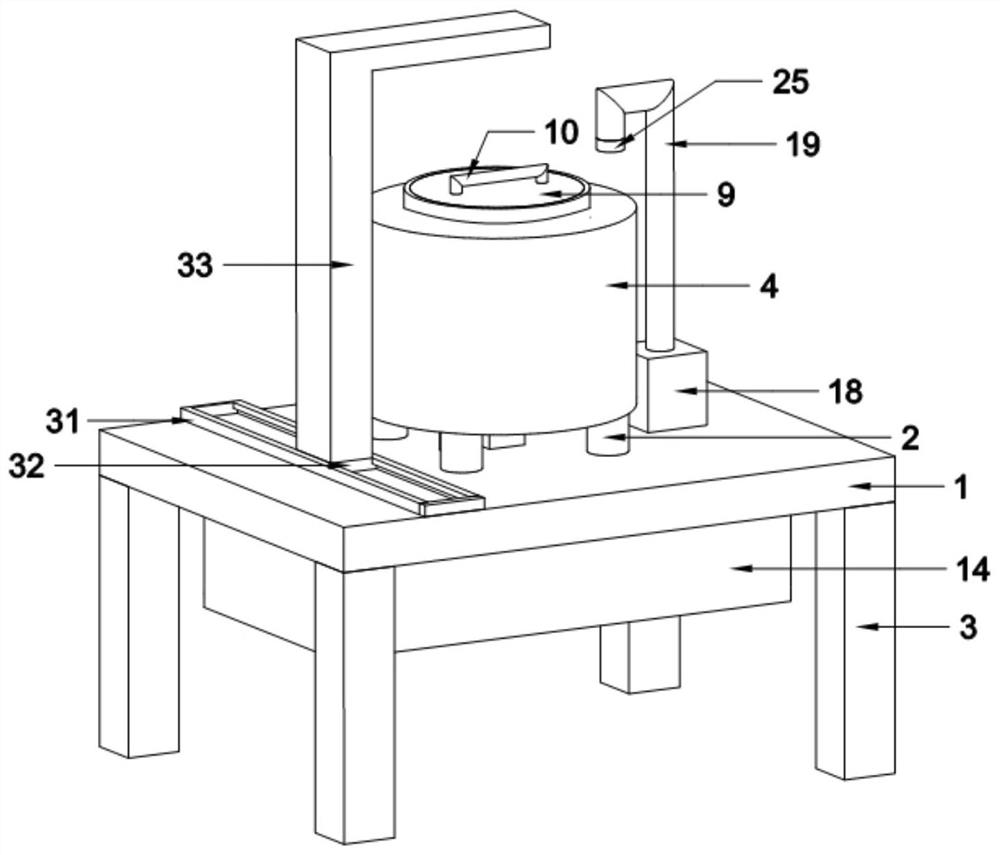
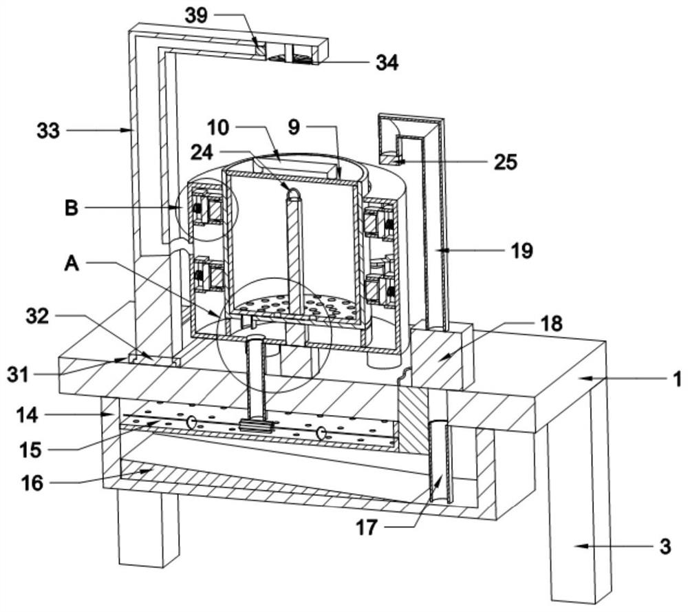
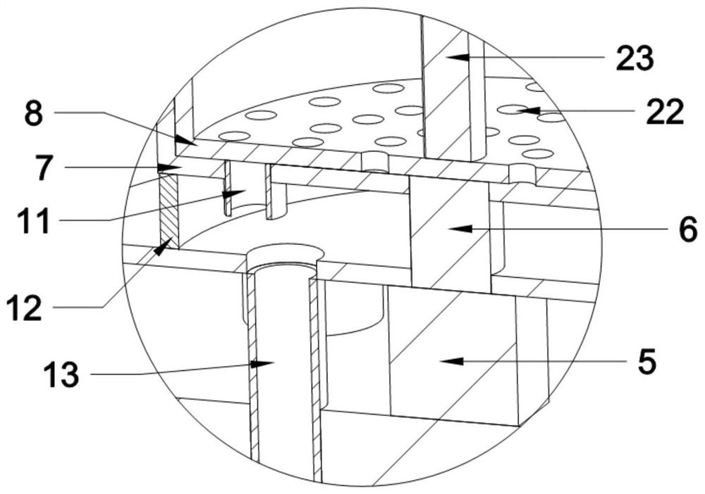
[0031] Such as Figure 1 to Figure 6As shown, the present invention provides a material cleaning device for stainless steel processing, including a support platform 1, a support rod 3 is provided at the bottom of the support platform 1, a fixed column 2 is provided at the top of the support platform 1, and a shock-absorbing barrel is provided at the top of the fixed column 2 4. The top of the supporting platform 1 is provided with a motor 5, the output shaft of the motor 5 is provided with a rotating shaft 6, and the top of the rotating shaft 6 is provided with a cleaning bucket 7, the outer surface of the rotating shaft 6 is rotationally connected with the shock absorbing barrel 4 through bearings, and the inner wall of the shock absorbing barrel 4 is provided with There is a square groove 26, the inner wall of the square groove 26 is slidably connected with a slider 27, and one side of the slider 27 is provided with two identical baffles 28, and the middle of the baffle 28 is...

no. 2 example

[0035] Basically, the first embodiment provides a material cleaning device for stainless steel processing. When the internal material is subjected to a constant centrifugal force during the rotation of the cleaning bucket 7, the storage state will not change again, so the material cannot be placed in the storage bucket 8 in all directions. Cleaning, and the plate-shaped material is not stirred and turned over so that the leak hole 22 is blocked and the cleaning water flow in the placement bucket 8 is not smooth, which affects the drainage and secondary flushing efficiency. In order to solve this problem, the material in the placement bucket 8 is not only It rotates under the action of centrifugal force, and can also be unevenly shaken left and right by the action of the shock-absorbing barrel 4 on the internal cleaning barrel 7 to ensure the cleaning effect of the internal materials. This kind of material cleaning device used in stainless steel processing has multiple The coeff...

no. 3 example

[0038] Based on the second implementation, a material cleaning device for stainless steel processing is provided. When the cleaned sewage enters the collection box 14 along the second sewage pipe 13 for recycling, filtration and reuse, only the elastic filter plate 15 is used to filter the sewage. , but in the process of use, the impurities in the sewage will block the filter port so that the drainage of the sewage is not smooth, or the sewage flow is too fast and the filter port of the flat elastic filter plate 15 is too slow to discharge water, so that when the sewage in the tank 12 accumulates The more, not only makes the water discharge in the bucket 8 slow, affecting the cleaning efficiency, but may even cause the sewage to flow into the shock-absorbing bucket 4 and affect the internal equipment. In order to solve this problem, ensure that the sewage inside the collection box 14 can be timely and effectively is recovered through the filtration of the elastic filter plate 1...


PUM


Abstract

The invention belongs to the technical field of cleaning devices, and discloses a material cleaning device for stainless steel machining. The material cleaning device comprises a supporting platform and a fixing column, supporting rods are arranged at the bottom of the supporting platform, the fixing column is arranged at the top of the supporting platform, a damping barrel is arranged at the top of the fixing column, a motor is arranged at the top of the supporting platform, a rotating shaft is arranged on an output shaft of the motor, a cleaning barrel is arranged at the top of the rotating shaft, the outer surface of the rotating shaft is rotationally connected with the damping barrel through a bearing, a first blow-off pipe is arranged at the bottom of the cleaning barrel, a water blocking groove is formed in the damping barrel and rotationally connected with the cleaning barrel through a supporting bearing, a water outlet of the first blow-off pipe is formed in the water blocking groove, and a second blow-off pipe is arranged at the bottom of the water blocking groove. Through the interaction of the cleaning barrel, a placing barrel, the damping barrel, a collecting box, a water outlet pipe and a supporting pipe, materials can be fully cleaned, the materials can be sprayed and dried, meanwhile, resources are effectively and repeatedly recycled, and the utilization rate of the resources is increased.

Description

technical field [0001] The invention belongs to the technical field of cleaning devices, in particular to a material cleaning device for stainless steel processing. Background technique [0002] Stainless steel is the abbreviation of stainless acid-resistant steel. The finished stainless steel has many advantages that ordinary metal workpieces do not have. It can withstand weak corrosive media such as air, steam and water, and has strong applicability. It is often used in household appliances and mechanical parts. and industrial supplies, etc., the history of stainless steel can be traced back to the First World War, and stainless steel in modern society has gradually become one of the indispensable metal parts in our production and life; but the cleaning effect of existing cleaning devices is Not good, after cleaning, when the material is taken out, the dirt after cleaning may still adhere to the surface, and there is still a lot of sewage from cleaning on the surface, whic...

Claims


Application Information

Patent Timeline
Patent Type & Authority Applications(China)
IPC IPC(8): B08B3/04B08B3/02B08B3/14B08B13/00F26B21/00
CPCB08B3/02B08B3/044B08B3/14B08B13/00F26B21/001F26B21/004
Inventor 徐敏旺
Owner 徐敏旺
Why Eureka
Try Eureka