
Smart plug remover

A blockage remover, intelligent technology, applied in the direction of electrode cleaning, chemical instruments and methods, cleaning methods and appliances, etc., can solve the problem of automatic detection and removal of nozzle blockage, inability to clean blockage conveniently and quickly, and inability to detect blockage in real time and other issues, to achieve the effect of zero error detection, convenient procurement, and strong adaptability

Inactive Publication Date: 2017-12-08
FUZHOU UNIV
View PDF6 Cites 0 Cited by
  • Summary
  • Abstract
  • Description
  • Claims
  • Application Information

AI Technical Summary

Problems solved by technology

The structure of the nozzle makes the spray particles fine and uniform, and the spray angle and spread range are larger than the previous structure. To a certain extent, the cleaning effect of the dust collecting pole of the wet electrostatic precipitator can be improved, and the number of nozzles can be appropriately reduced. At the same time It can effectively reduce water consumption and avoid nozzle wear, improve the efficiency of dust removal in general, save equipment investment and operating costs, and is economical, but there are still certain defects in automatic detection of nozzle clogging, and it is difficult to enter the environment manually Unable to realize automatic detection and unclogging of nozzle clogging
Zhejiang Feida Environmental Protection Technology Co., Ltd. proposed a double-sided directional nozzle for wet electrostatic precipitators. The outlet tank with connected holes can solve the problem of nozzle clogging to a certain extent
However, it is impossible to clean the blockage conveniently and quickly in an environment where blockage has already occurred and cannot be entered manually. At the same time, it is impossible to detect whether blockage has occurred in real time.

Method used


Image

  • Smart plug remover
  • Smart plug remover
  • Smart plug remover

Examples


Embodiment Construction

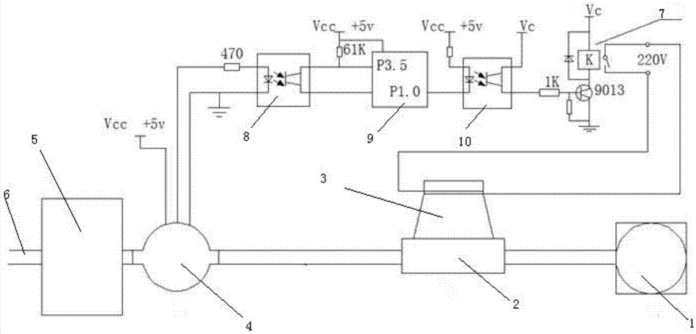
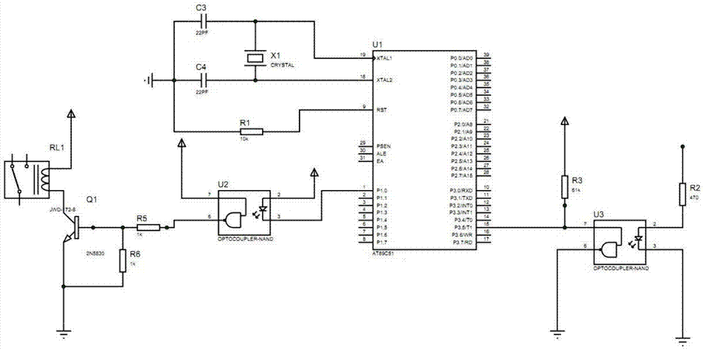
[0016] The present invention provides an intelligent blockage remover. For the structural and principle block diagram, please refer to figure 1 . For a structural diagram of an embodiment of the present invention, see figure 2 . The device comprises a settling box 5, a three-way interface 2, a Hall flowmeter 4, a first photoelectric coupling circuit 8, a second photoelectric coupling circuit 10, a single-chip microcomputer 9, a relay 7 and an ultrasonic vibrator 3; One interface is connected to the inlet of the spray nozzle 1 of the wet electrostatic precipitator, the second interface of the three-way interface 2 is connected to the Hall flowmeter 4, and the third interface of the three-way interface 2 is connected to the ultrasonic vibrator 3; After the Hall flowmeter 4 is installed in the outlet pipe of the settling tank 5, the Hall flowmeter 4 is connected with the input port of the single-chip microcomputer 9 through the first photoelectric coupling circuit 8, and the s...


PUM


Abstract

The object of the present invention is to provide an intelligent blockage remover, which includes a settling tank, a three-way interface, a Hall flowmeter, a first photoelectric coupling circuit, a second photoelectric coupling circuit, a single-chip microcomputer, a relay and an ultrasonic vibrator; the three-way interface The first interface of the three-way interface is connected to the inlet of the spray nozzle of the wet electrostatic precipitator, the second interface of the three-way interface is connected to the Hall flowmeter, and the third interface of the three-way interface is connected to the ultrasonic vibrator; the Hall flowmeter is installed on the outlet pipe of the sedimentation tank Finally, the Hall flowmeter is connected to an input port of the single-chip microcomputer through the first photoelectric coupling circuit, and an output port of the single-chip microcomputer is connected to the input of the relay through the second photoelectric coupling circuit; the output of the relay is connected to the ultrasonic vibrator. The Hall flowmeter can judge whether the nozzle is blocked by detecting the flow rate of the liquid flowing in 1s. If it is blocked, it will control the single-chip microcomputer to control the switch of the ultrasonic vibrator to realize the online cleaning of the nozzle. If there is no blockage, will continue to be detected.

Description

technical field [0001] The invention relates to the technical field of automatic detection and control, and relates to a device for automatically cleaning pipeline blockages. More specifically, the invention relates to an intelligent blockage remover for fully automatic detection and control of online cleaning of spray nozzles of wet electrostatic precipitators. Background technique [0002] The spray nozzles of wet electrostatic precipitators are prone to clogging. The nozzles are all installed inside the wet electrostatic precipitator. When the furnace is not in operation, it is full of smoke and cannot be entered manually. The existing blockage removal method has to manually remove the blockage after the machine is shut down. [0003] In China, Shanghai Longjing Environmental Protection Technology Engineering Co., Ltd. proposed a spiral nozzle and its arrangement structure suitable for wet electrostatic precipitators. Its role is mainly to achieve the ultra-fine atomizat...

Claims


Application Information

Patent Timeline
Patent Type & Authority Patents(China)
IPC IPC(8): B03C3/34B08B3/12B03C3/78
Inventor 雷瑶罗创王兆权林起本郑焜耀唐长明
Owner FUZHOU UNIV
Learn More