Catalytic cracking regeneration flue gas dry type desulfurization and denitrification dust removal system
A technology for regenerating flue gas, desulfurization and denitrification, applied in the field of desulfurization and denitrification integration, can solve the problems of difficult wastewater treatment, environmental impact, large amount of dust, etc., and achieve the effects of easy disassembly and replacement, improved efficiency, and energy saving
- Summary
- Abstract
- Description
- Claims
- Application Information
AI Technical Summary
Problems solved by technology
Method used
Image
Examples
Embodiment 1
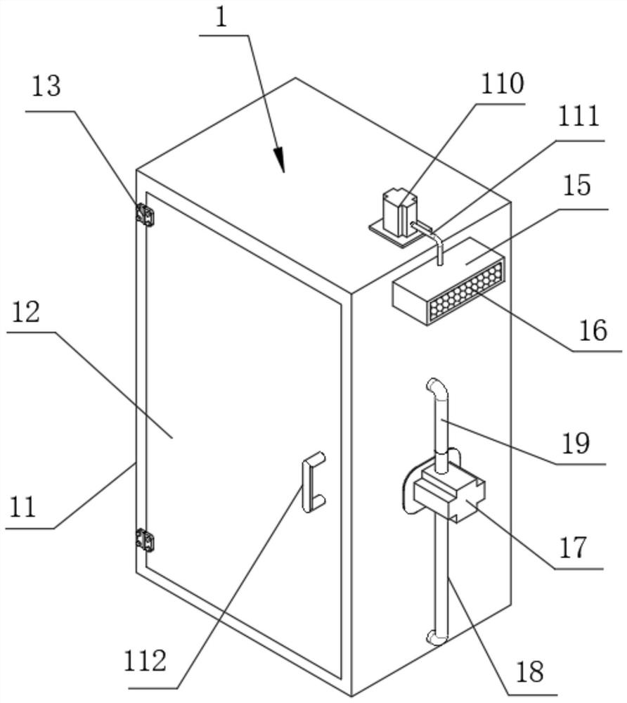
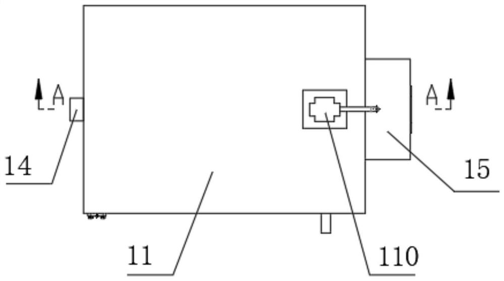
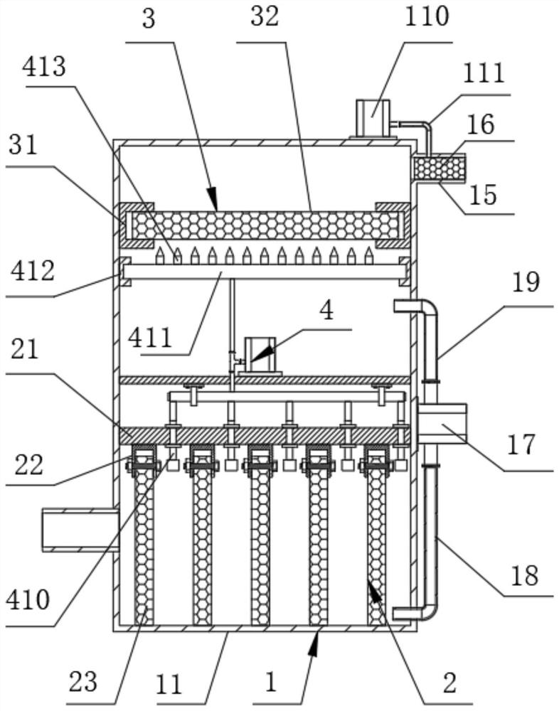
[0046] see Figure 1-Figure 9 , the present invention provides a technical solution:
[0047] Such as Figure 1-Figure 9 As shown, a catalytic cracking regenerated flue gas dry desulfurization, denitrification and dust removal system includes:
[0048]Dust removal base mechanism 1, desulfurization mechanism 2 and denitrification mechanism 3.
[0049] In order to facilitate the removal of sulfur, nitrate and dust in the flue gas, the middle part of the outer wall of one side of the dust filter box 11 is fixedly connected with a first induced draft fan 17, and the air intake end of the first induced draft fan 17 is equipped with a suction pipe 18 One end of the suction pipe 18 runs through the bottom of the dust filter box 11 and communicates with the inner cavity of the dust filter box 11. The outlet end of the first induced draft fan 17 is equipped with an air outlet pipe 19, and one end of the air outlet pipe 19 runs through the dust filter. The upper part of the box body ...
Embodiment 2
[0052] see Figure 1-Figure 9 The difference between Embodiment 2 and Embodiment 1 is that a dredging mechanism 4 is installed in the middle of the inner cavity of the dust filter box 11, and the dredging mechanism 4 includes a support plate 41, and the support plate 41 is installed in the middle of the inner cavity of the dust filter box 11. The sidewalls on both sides of the support plate 41 are fixedly connected to both sides of the inner wall of the dust filter box 11, and the top side of the support plate 41 is fixedly connected with a third induced draft fan 42, and the outlet end of the third induced draft fan 42 is equipped with a tee joint 43, The two branch ends of the three-way joint 43 are respectively equipped with a lower connecting pipe 44 and an upper connecting pipe 45, and one end of the lower connecting pipe 44 runs through the support plate 41;
[0053] Wherein, a first trunk pipe 46 is horizontally arranged below the support plate 41, and both ends of the ...
Embodiment 3
[0059] see Figure 1-Figure 9 The difference between Embodiment 3 and Embodiment 1 and Embodiment 2 is that in order to further filter and absorb the dust in the flue gas, an exhaust port is installed on the upper part of the side wall of the dust filter box 11 away from the air inlet 14 15. An air port filter 16 is installed in the exhaust port 15. When the flue gas flows out, the dust can be filtered through the air port filter 16 again.
[0060] In order to ensure that the operator can replace the air port filter 16 at a later stage, the air port filter 16 is detachably connected to the exhaust port 15, which is convenient for the operator to disassemble and replace the air port filter 16.
[0061] In order to facilitate the outward transportation of the flue gas, the dust filter box 11 is fixedly connected with a second induced draft fan 110 on the top side of the exhaust port 15, and the intake end of the second induced draft fan 110 is connected with an air intake pipe 1...
PUM
| Property | Measurement | Unit |
|---|---|---|
| pore size | aaaaa | aaaaa |
Abstract
Description
Claims
Application Information
 - R&D
- Intellectual Property
- Life Sciences
- Materials
- Tech Scout
- Unparalleled Data Quality
- Higher Quality Content
- 60% Fewer Hallucinations
Browse by: Latest US Patents, China's latest patents, Technical Efficacy Thesaurus, Application Domain, Technology Topic, Popular Technical Reports.
© 2025 PatSnap. All rights reserved.Legal|Privacy policy|Modern Slavery Act Transparency Statement|Sitemap|About US| Contact US: help@patsnap.com


