Environment-friendly recycling, crushing and separating equipment for waste electronic components
A technology for electronic components and separation equipment, applied in the field of environmental protection recycling of waste electronic components and crushing and separation equipment, can solve the problems of poor crushing effect of crushing and separation equipment, and achieve the goal of improving crushing efficiency and quality, improving discharging efficiency and avoiding pollution. Effect
- Summary
- Abstract
- Description
- Claims
- Application Information
AI Technical Summary
Problems solved by technology
Method used
Image
Examples
Embodiment 1
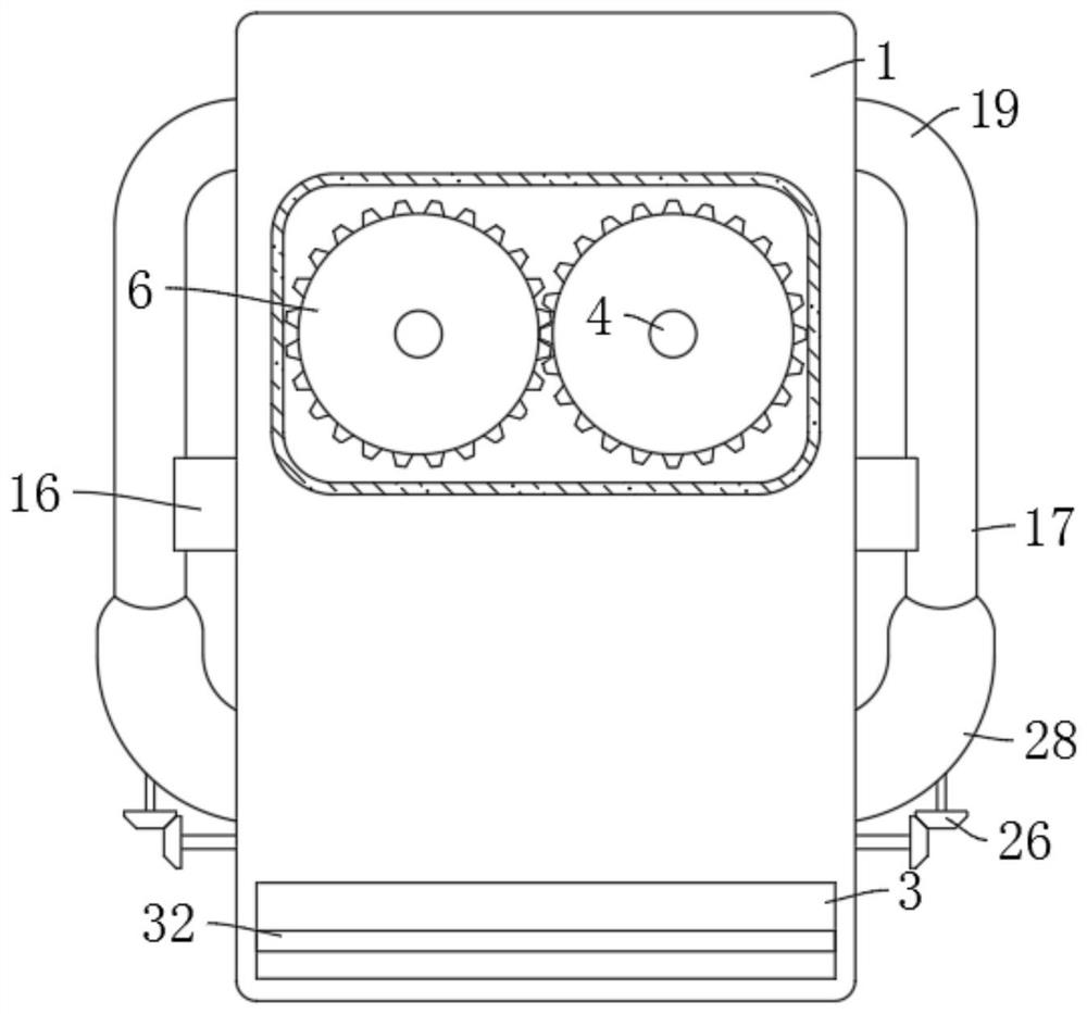
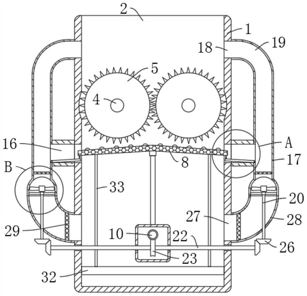
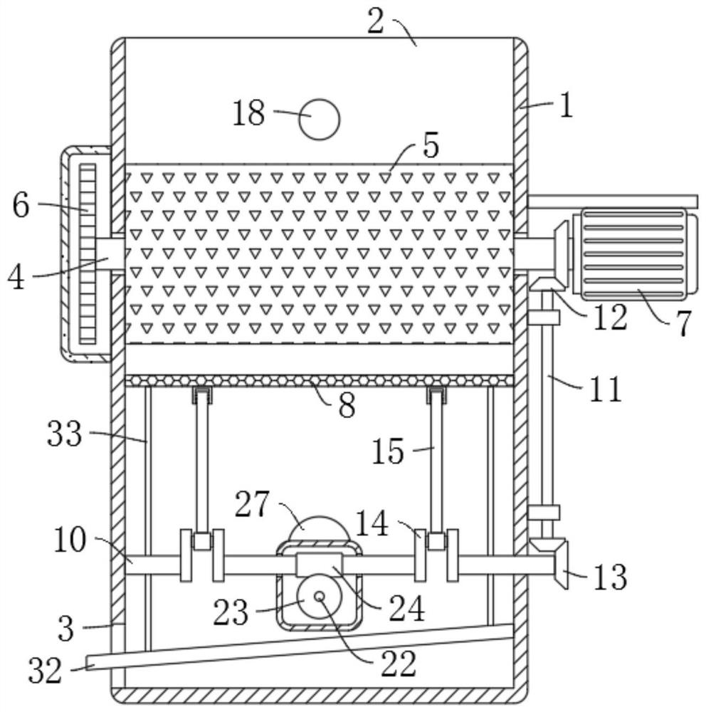
[0033] refer to Figure 1-6 , an environmentally friendly recycling, crushing and separation equipment for waste electronic components, comprising a box body 1, the upper end of the box body 1 is provided with a feeding port 2, the lower end side wall of the box body 1 is provided with a discharge port 3, and the material passing through the feeding port 2 The two rotating shafts 4 are rotatably connected with two cooperating crushing rollers 5, and the two rotating shafts 4 are meshed and connected by two first gears 6. The side wall of the box body 1 is fixedly equipped with a motor 7, and the output end of the motor 7 is connected to the One end of one of the rotating shafts 4 is fixedly connected, the lower end of the crushing roller 5 is provided with a screening plate 8 which is slidingly connected with the box body 1, and the two sides of the upper end of the screening plate 8 are inclined downward. The chute 9 matched with the plate 8, the lower end of the screening pl...
Embodiment 2
[0035] refer to figure 2 and image 3, is basically the same as Embodiment 1, furthermore: the shaking mechanism includes a first rotating rod 10 that is rotatably connected to the inner wall of the box body 1, a crankshaft 14 is fixedly installed in the middle of the first rotating rod 10, and a connecting rod is rotatably connected to the crankshaft 14 15. The other end of the connecting rod 15 is rotatably connected to the lower end of the screening plate 8. The side wall of the box body 1 is rotatably connected to the second rotating rod 11 through the support. One end of the second rotating rod 11 and one of the rotating shafts 4 pass through The two second gears 12 are meshed and connected, and the other end of the second rotating rod 11 is meshed with the first rotating rod 10 through two third gears 13. During the rotation of the rotating shaft 4, the rotating shaft 4 will pass through the two second gears. 12 drives the second rotating rod 11 to rotate, the second r...
Embodiment 3
[0039] refer to figure 2 , Figure 4 , Figure 5 and Figure 6 , is basically the same as Embodiment 1, furthermore: the automatic recovery mechanism includes a cluster cover 16 fixedly connected to the outer walls of the two chutes 9, and the ends of the two cluster covers 16 are fixedly connected with a recovery cylinder 17 communicating with it, The side wall of the feeding port 2 is provided with two recovery ports 18 corresponding to the cluster cover 16, and the upper ends of the two recovery cylinders 17 are respectively fixedly connected with the two recovery ports 18 through an arc-shaped tube 19, and the two recovery cylinders The inner wall of the lower end of the cylinder 17 is connected with the fourth rotating rod 20 through the bracket rotation, the upper ends of the two fourth rotating rods 20 are fixedly installed with blowing fan blades 21, and the lower end inner wall of the box body 1 is connected with the fifth rotating rod 22 in rotation. , the middle...
PUM
 Abstract
Description
Claims
Application Information
 - R&D
- Intellectual Property
- Life Sciences
- Materials
- Tech Scout
- Unparalleled Data Quality
- Higher Quality Content
- 60% Fewer Hallucinations
Browse by: Latest US Patents, China's latest patents, Technical Efficacy Thesaurus, Application Domain, Technology Topic, Popular Technical Reports.
© 2025 PatSnap. All rights reserved.Legal|Privacy policy|Modern Slavery Act Transparency Statement|Sitemap|About US| Contact US: help@patsnap.com


