Rapid powder point equipment applied to lining cloth and used for garment production

A technology of powder spot and interlining, which is applied to the device for coating liquid on the surface, pretreatment surface, coating, etc., can solve the problems of wasting manpower, high labor intensity, and difficult to control the speed to be completely consistent, so as to maintain the discharge rate. Consistent speed and improved effect

Active Publication Date: 2021-03-09
泉州台商投资区笙沓新材料有限公司
View PDF11 Cites 0 Cited by
  • Summary
  • Abstract
  • Description
  • Claims
  • Application Information

AI Technical Summary

Problems solved by technology

[0006] In order to overcome the disadvantages of manually discharging the interlining cloth with powder dot coating, which is a waste of manpower, the labor intensity is high, and it is difficult to control the speed to be completely consistent, the technical problem to be solved by the present invention is to provide an automatic Unwinding, fast powder dot equipment for interlinings in garment production that can maintain consistent unwinding speed

Method used


Image

  • Rapid powder point equipment applied to lining cloth and used for garment production
  • Rapid powder point equipment applied to lining cloth and used for garment production
  • Rapid powder point equipment applied to lining cloth and used for garment production

Examples


Embodiment 1

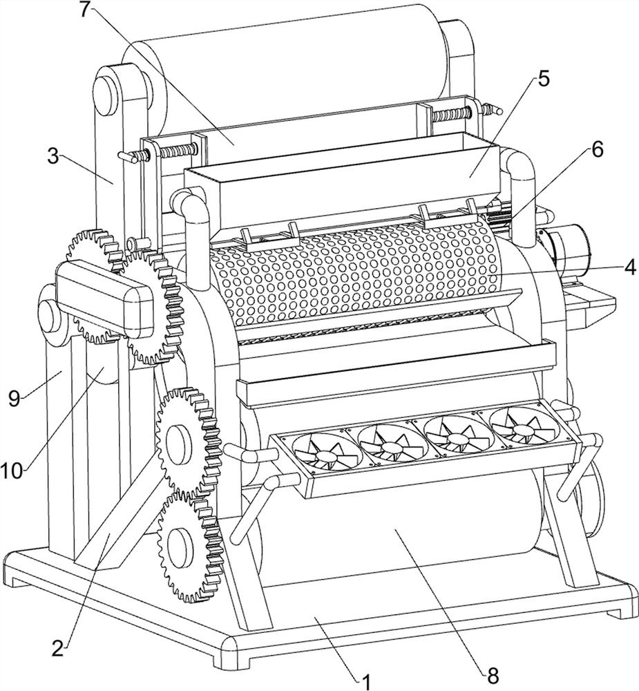
[0030] A fast powder-pointing equipment for interlining for garment production, such as figure 1 , figure 2 , image 3 and Figure 5 As shown, it includes a bottom plate 1, a bracket 2, an installation and placement component 3, a powder spot component 4, a material storage component 5 and an interval blanking component 6. The left and right sides of the rear side of the top of the bottom plate 1 are connected with brackets 2. An installation and placement assembly 3 is installed between the two, on which a powder spot assembly 4 and a material storage assembly 5 are respectively installed, and an interval blanking assembly 6 is installed on the right bracket 2 .

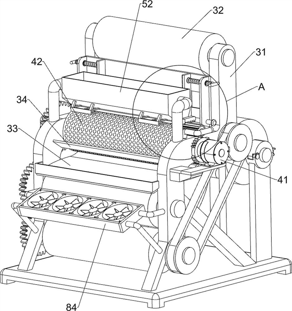
[0031] The installation and placement assembly 3 includes an installation frame 31, a rotating roller 32, a pallet frame 33, a scraper plate 34 and a guide plate 35. The installation frame 31 is connected to the bracket 2, the bottom of the installation frame 31 is connected to the top of the bottom plate 1, and ...

Embodiment 2

[0037] On the basis of Example 1, as figure 1 , Figure 4 and Figure 5 As shown, it also includes a guide assembly 7. The guide assembly 7 includes a third fixing frame 71, a slotted baffle frame 72, a sliding side plate 73, a screw rod 74, a fixing nut 75 and a guide rod 76. The upper part of the inner side of the mounting frame 31 A third fixing frame 71 is connected, and a slotted baffle frame 72 is connected between the two third fixing frames 71. The left and right sides of the slotted baffle frame 72 are slidably connected with sliding side plates 73. The left and right sides of the plate frame 72 are connected with fixed nuts 75, and the fixed nuts 75 are connected with screw rods 74 by means of screw connection. , the guide rod 76 is slidably connected with the slotted baffle frame 72 .

[0038] According to the size of the interlining cloth 10, the screw 74 can be rotated to make the sliding side plate 73 move inward and contact the side of the interlining cloth 1...

Embodiment 3

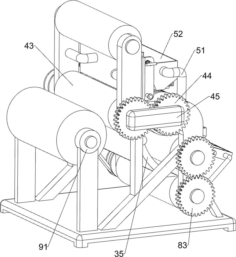
[0040] On the basis of Example 2, as Figure 1-4 As shown, it also includes a compaction cooling assembly 8. The compaction cooling assembly 8 includes a transmission belt group 81, a pressing roller 82, a second opposing gear group 83 and a fan cooling frame 84, and the mounting frame 31 is rotatably connected with a Two pressing rollers 82, a transmission belt group 81 is connected between the lower pressing roller 82 and the flat heating roller 43, a second opposing gear group 83 is connected between the two pressing rollers 82, and the front side of the mounting frame 31 is connected There are fan cooling racks 84 .

[0041] The lining cloth 10 after powder dot coating enters between the pressing rollers 82 through the guide plate 35, and the flat heating roller 43 rotates in the reverse direction through the transmission belt group 81 to make the lower side pressing roller 82 rotate in the reverse direction, through the second opposing gear group 83. The upper side press...


PUM


Abstract

The invention relates to powder point equipment, in particular to rapid powder point equipment applied to lining cloth and used for garment production, and provides the rapid powder point equipment which is applied to the lining cloth and used for garment production, can automatically discharge materials and can keep the consistent discharging speed. The rapid powder point equipment applied to thelining cloth and used for garment production comprises a bottom plate, a mounting and placing assembly, a powder point assembly, a material storage assembly and an intermittent discharging assembly;supports are connected to the two sides of the bottom plate; the mounting and placing assembly is mounted between the supports; the powder point assembly is mounted on the mounting and placing assembly; the material storage assembly is mounted on the mounting and placing assembly; and the intermittent discharging assembly is mounted on the support on one side. According to the equipment, powder can be stored through the material storage assembly, and intermittent discharging can be achieved through the intermittent discharging assembly, so that the powder intermittently falls onto the powder point assembly; powder point coating can be conducted on the lining cloth through the powder point assembly, and powder point coating work can be conveniently conducted through the mounting and placingassembly.

Description

technical field [0001] The invention relates to a powder-pointing device, in particular to a fast powder-pointing device for lining cloth for garment production. Background technique [0002] The interlining is based on woven fabrics, knitted fabrics and non-woven fabrics, using (or not using) thermoplastic polymer compounds, and is specially processed by special machinery to strengthen and stiffen the inner layer of clothing. Special clothing accessories that are bonded (or non-bonded) to fabrics. Among them, the adhesive interlining is made by uniformly coating the polymer hot melt adhesive on organic fabrics, knitted fabrics and non-woven fabrics through special coating equipment. The coating of the adhesive interlining is usually divided into powder spots Coating, paste point coating, dust coating and double point coating. [0003] In the prior art, when powder coating the lining cloth, it is generally necessary to manually discharge the material. When manually dischar...

Claims


Application Information

Patent Timeline
IPC IPC(8): B05C19/04B05C19/06B05C13/02B05C9/14B05C11/02B05D3/04
CPCB05C19/04B05C19/06B05C13/02B05C9/14B05C11/025B05D3/0426
Inventor 余培峰
Owner 泉州台商投资区笙沓新材料有限公司
Why Eureka
Try Eureka