Clamp with double positioning structures for computer equipment machining

A technology of computer equipment and positioning structure, which is applied in the direction of manufacturing tools, workpiece clamping devices, cleaning methods and utensils, etc., can solve the problems of precise positioning and clamping of computer equipment, failure of computer equipment processing, easy damage of computer equipment, etc., and achieve saving A lot of time, the clamping process is simple and fast, and the effect of reducing the error rate

Inactive Publication Date: 2021-03-09
广州天域科技有限公司
View PDF0 Cites 0 Cited by
  • Summary
  • Abstract
  • Description
  • Claims
  • Application Information

AI Technical Summary

Problems solved by technology

[0004] The purpose of the present invention is to provide a fixture with a double positioning structure for computer equipment processing, to solve the problem that the existing fixture can only clamp and fix the computer equipment in the above background technology, and cannot accurately position the computer equipment. It is easy to cause the failure of computer equipment processing, reduce work efficiency, and increase processing costs. At the same time, the fixture is easy to damage the computer equipment during the clamping process, which cannot meet people's needs.

Method used


Image

  • Clamp with double positioning structures for computer equipment machining
  • Clamp with double positioning structures for computer equipment machining
  • Clamp with double positioning structures for computer equipment machining

Examples


Embodiment Construction

[0046] The following will clearly and completely describe the technical solutions in the embodiments of the present invention with reference to the accompanying drawings in the embodiments of the present invention. Obviously, the described embodiments are only some, not all, embodiments of the present invention. Based on the embodiments of the present invention, all other embodiments obtained by persons of ordinary skill in the art without making creative efforts belong to the protection scope of the present invention.

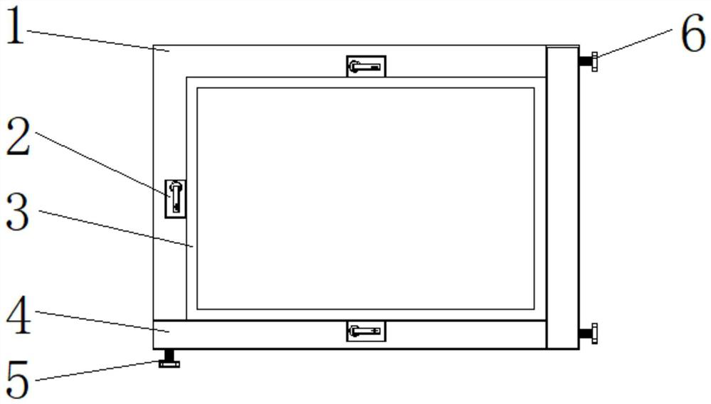
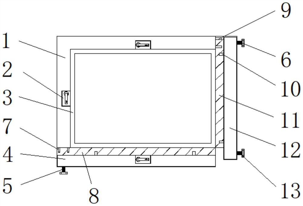
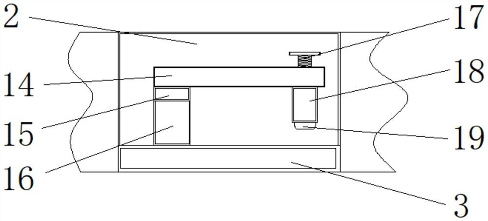
[0047] see Figure 1-5 , the present invention provides a technical solution: a fixture with a double positioning structure for computer equipment processing, including a limit frame 1 and a second slide rail 22, a fixing groove 2 is arranged inside the limit frame 1, and the fixing groove 2 supporting plate 3 is installed on the right side of the supporting plate 3, the first limit control plate 4 is installed on the lower end of the supporting plate 3, and t...


PUM


Abstract

The invention discloses a clamp with double positioning structures for computer equipment machining. The clamp with the double positioning structures for computer equipment machining comprises a limiting frame and a second sliding rail, wherein a fixing groove is formed in the limiting frame, a supporting plate is arranged on the right side of the fixing groove, a first limiting control plate is arranged at the lower end of the supporting plate, and a second limiting control plate is arranged at the right end of the first limiting control plate. The detachable first limiting control panel is arranged, and is pushed to move outwards by unscrewing first threaded nails, so that computer hardware to be machined is placed on the supporting plate; and meanwhile, the first limiting control panelcan be fixed through the first threaded nails, so that the computer hardware to be machined is fixed. Therefore, the clamping process of a computer workpiece to be machined becomes simple and rapid, alarge amount of time can be saved, and the working efficiency is improved; and the limiting frame plays a role in limiting and positioning the computer workpiece to be machined, so that the computerworkpiece can be conveniently and accurately positioned and machined, and the machining efficiency is improved.

Description

technical field [0001] The invention relates to the technical field of computer equipment processing, in particular to a fixture with a double positioning structure for computer equipment processing. Background technique [0002] Computer, commonly known as computer, is a modern electronic computing machine used for high-speed computing. It can perform numerical calculations, logic calculations, and storage and memory functions. It is a modern intelligent electronic device that can run according to programs and process massive amounts of data automatically and at high speed. Equipment, and fixtures are often used in the processing of computer equipment. This fixture is used to fix computer equipment during the manufacturing process so that it can occupy the correct position for processing. [0003] Existing fixtures can only clamp and fix computer equipment, but cannot accurately position and clamp computer equipment, which will easily lead to failure of computer equipment p...

Claims


Application Information

Patent Timeline
Patent Type & Authority Applications(China)
IPC IPC(8): B08B7/00B08B13/00B25B11/00
CPCB08B7/0042B08B13/00B25B11/00
Inventor 陈丽玲
Owner 广州天域科技有限公司
Why Eureka
Try Eureka