Full-automatic plate bending method

A fully automatic, plate technology, used in safety equipment, metal processing equipment, manufacturing tools, etc., can solve the problems of inability to adjust the bending angle, no protective devices, unqualified products, etc., to achieve enhanced practicability and increased safety. , the effect of reducing safety accidents

Inactive Publication Date: 2021-03-09
WUHAN UNIV OF SCI & TECH
View PDF0 Cites 2 Cited by
  • Summary
  • Abstract
  • Description
  • Claims
  • Application Information

AI Technical Summary

Problems solved by technology

[0004] Aiming at the deficiencies of the prior art, the present invention provides a fully automatic plate bending method, which solves the problems that the bending angle cannot be adjusted, there is no protective device during bending, and the plate rebounds after bending, resulting in unqualified products

Method used


Image

  • Full-automatic plate bending method
  • Full-automatic plate bending method
  • Full-automatic plate bending method

Examples


Embodiment 1

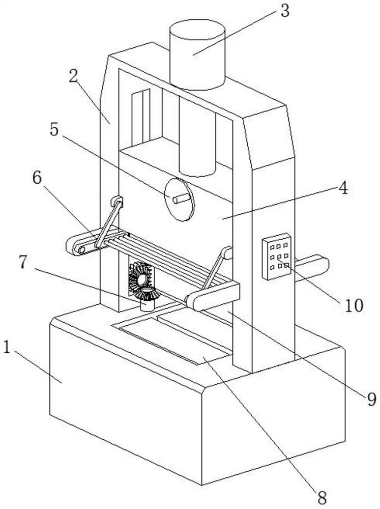
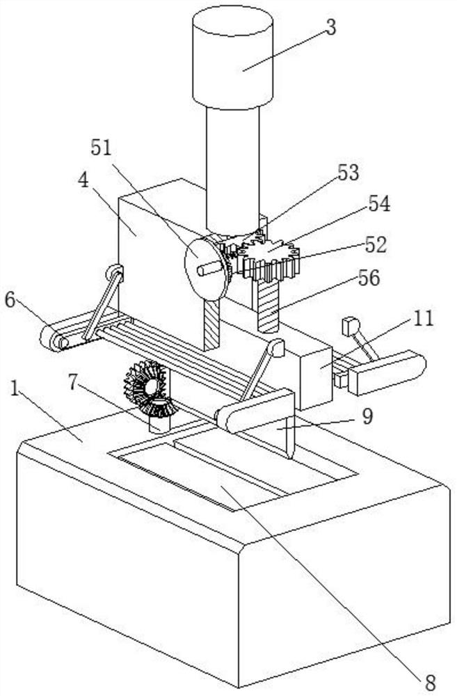
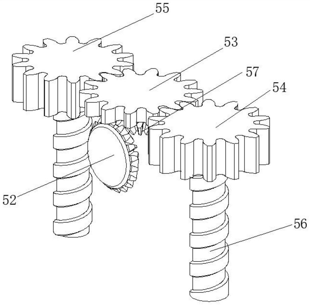
[0038] A fully automatic plate bending method, such as Figure 1-Figure 5 As shown, it includes workbench 1, the top of workbench 1 is welded with support column 2, the top of support column 2 is connected with oil cylinder 3 through bolts, the inner wall of support column 2 is slidably connected with slide plate 4, and the front part of slide plate 4 is provided with adjustment Mechanism 5, the front of the support column 2 is provided with a protective mechanism 6, the top of the workbench 1 is provided with a discharge mechanism 7, and the discharge mechanism 7 is located on the right side of the support column 2, and the inside of the workbench 1 is provided with a discharge mechanism 8. The right side of the support column 2 is connected with the controller 10 by bolts, the inner wall of the slide plate 4 is slidably connected with the slider 11, the bottom of the slide block 11 is welded with the top block 9, and the output end of the oil cylinder 3 is welded and fixed to...

Embodiment 2

[0045] Such as Figure 5-Figure 7 As shown, the lower surface of the scraper 71 is rotatably connected to the top of the workbench 1, the axis of the transmission gear 74 is rotatably connected to the inner wall of the support column 2, and the surface of the rack 75 is connected to the inner wall of the support column 2 and the workbench 1 respectively. Sliding connection, after the bending is completed, the scraper 71 will be reset, and the unloaded sheet will be pushed out at the same time, so that the worker does not need to manually remove the unloaded material, which can increase work efficiency, and only needs to be loaded all the time. Yes, it can also reduce the occurrence of safety accidents, greatly increase the safety, and ensure the personal safety of workers.

[0046] It is worth noting that the unloading mechanism 8 includes a telescopic column 81, the surface of the telescopic column 81 is sleeved with a return spring 82, the top of the telescopic column 81 is ...


PUM


Abstract

The invention relates to the technical field of bending devices, and discloses a method for bending a plate through a full-automatic plate bending device. The bending device comprises a workbench; a supporting column is welded to the top of the workbench; an oil cylinder is connected to the top of the supporting column through a bolt; a sliding plate is slidably connected to the inner wall of thesupporting column; an adjusting mechanism is arranged on the front portion of the sliding plate; a protection mechanism is arranged on the front portion of the supporting column; a discharging mechanism is arranged on the top of the workbench; and an unloading mechanism is arranged in the workbench. The height of a top block can be adjusted through the adjusting mechanism, so that the moving distance of the top block in the same stroke is shortened, then the bending angle of a plate material is changed, so that the bending angle can be adjusted, and application to plate material bending at different angles is achieved; the two ends of the device can be blocked during bending through the protection mechanism, hands are prevented from accidentally stretching into the device in the bending process, potential safety hazards are reduced, and the safety of workers is guaranteed.

Description

technical field [0001] The invention relates to the technical field of bending devices, in particular to a fully automatic plate bending method. Background technique [0002] Bending machine is a machine that can bend thin plates. The bending equipment currently on the market can only bend workpieces with fixed angles. If you need to bend workpieces with different angles, you need to replace different bending machines. The practicability of the device is greatly reduced, the scope of application is low, and there is no protective device during bending, which poses a safety hazard. Even if a protective device is added, the worker usually needs to manually control the opening and closing of the protective device. If the worker forgets to open the protective device Devices are prone to safety accidents. If an automatic protection device is used, an additional drive device is required to control the opening and closing of the protection device, which often increases the cost; th...

Claims


Application Information

Patent Timeline
IPC IPC(8): B21D5/00B21D45/02B21D55/00
CPCB21D5/00B21D45/02B21D55/00
Inventor 郝志强
Owner WUHAN UNIV OF SCI & TECH
Why Eureka
Try Eureka