Rotary driving mechanism
A technology of rotating drive mechanism and rotating drive components, applied in auxiliary devices, auxiliary welding equipment, welding/cutting auxiliary equipment, etc., can solve the problems of high work intensity and low work efficiency of staff
- Summary
- Abstract
- Description
- Claims
- Application Information
AI Technical Summary
Problems solved by technology
Method used
Image

Examples
Embodiment 1
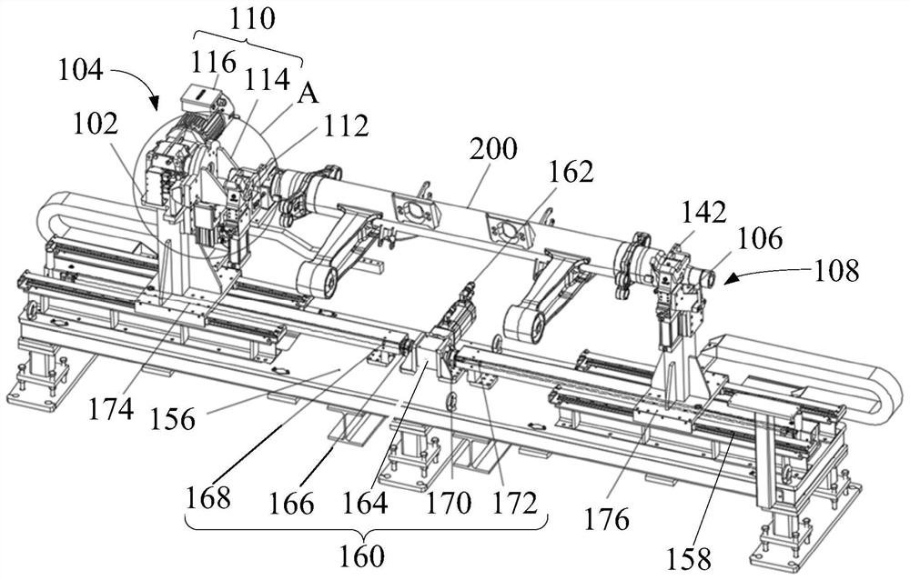
[0060] like figure 1 , figure 2 and image 3 As shown, the first embodiment of the present invention provides a rotary drive mechanism, including: a first frame body 102 , a first actuator 104 , a second frame body 106 and a second actuator 108 .
[0061] The first actuator 104 is arranged on the first frame body 102, the second actuator 108 is arranged on the second frame body 106, and the second frame body 106 and the first frame body 102 are arranged at intervals, so that the first actuator There is an execution space between 104 and the second actuator 108 . During the operation of the rotary drive mechanism, the first actuator 104 and the second actuator 108 clamp both ends of the workpiece 200 respectively to ensure the positioning of the workpiece 200; then the first actuator 104 rotates relative to the first frame body 102, And drive the workpiece 200 to rotate. In particular, the rotation axis of the workpiece 200 extends from the first actuator 104 toward the sec...
Embodiment 2
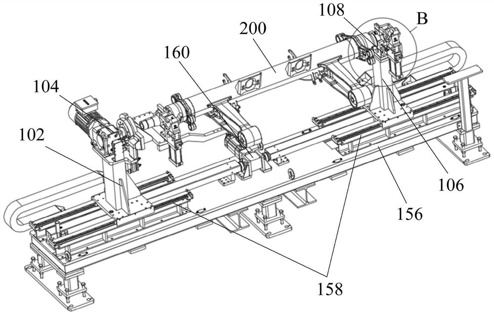
[0065] like figure 1 , figure 2 and image 3 As shown, the second embodiment of the present invention provides a rotary drive mechanism, including: a first frame body 102 , a first actuator 104 , a second frame body 106 and a second actuator 108 .
[0066] Wherein, the first actuator 104 is provided on the first frame body 102 , and the second actuator 108 is provided on the second frame body 106 . During the operation of the rotary drive mechanism, the first actuator 104 and the second actuator 108 clamp both ends of the workpiece 200 respectively to ensure the positioning of the workpiece 200; then the first actuator 104 rotates relative to the first frame body 102, And drive the workpiece 200 to rotate. In particular, the rotation axis of the workpiece 200 extends from the first actuator 104 toward the second actuator 108 to realize the automatic turning of the workpiece 200, so that the workpiece 200 can be completely displayed to the staff on the side of the workpiece ...
Embodiment 3
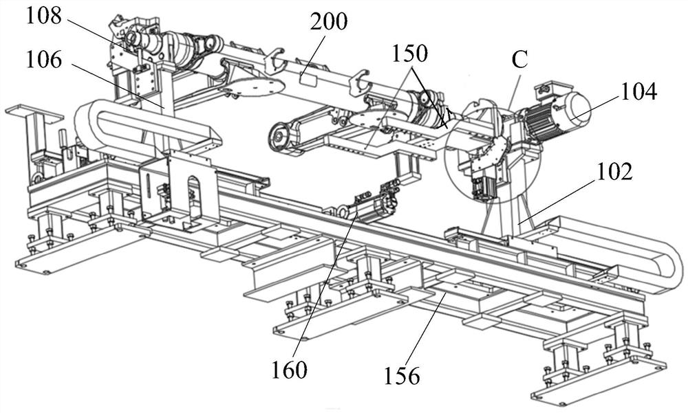
[0073] like figure 1 , figure 2 and image 3 As shown, the third embodiment of the present invention provides a rotary drive mechanism, including: a first frame body 102 , a first actuator 104 , a second frame body 106 and a second actuator 108 .
[0074] Wherein, the first actuator 104 is provided on the first frame body 102 , and the second actuator 108 is provided on the second frame body 106 . During the operation of the rotary drive mechanism, the first actuator 104 and the second actuator 108 clamp both ends of the workpiece 200 respectively to ensure the positioning of the workpiece 200; then the first actuator 104 rotates relative to the first frame body 102, And drive the workpiece 200 to rotate. In particular, the rotation axis of the workpiece 200 extends from the first actuator 104 toward the second actuator 108 to realize the automatic turning of the workpiece 200, so that the workpiece 200 can be completely displayed to the staff on the side of the workpiece 2...
PUM
 Abstract
Description
Claims
Application Information
 - R&D
- Intellectual Property
- Life Sciences
- Materials
- Tech Scout
- Unparalleled Data Quality
- Higher Quality Content
- 60% Fewer Hallucinations
Browse by: Latest US Patents, China's latest patents, Technical Efficacy Thesaurus, Application Domain, Technology Topic, Popular Technical Reports.
© 2025 PatSnap. All rights reserved.Legal|Privacy policy|Modern Slavery Act Transparency Statement|Sitemap|About US| Contact US: help@patsnap.com