Vibration detection device for mechanical arm manufacturing

A vibration detection, robotic arm technology, applied in manipulators, manufacturing tools, etc., can solve the problems of uncontrollable, damaged robotic arm stability, low vibration frequency, etc., to increase stability, improve convenience, and facilitate movement.

Inactive Publication Date: 2021-03-09
程卫清
View PDF6 Cites 0 Cited by
  • Summary
  • Abstract
  • Description
  • Claims
  • Application Information

AI Technical Summary

Problems solved by technology

[0005] The purpose of the present invention is to provide a vibration detection device manufactured by a mechanical arm, which solves the existing problems of low vibration frequency and uncontrollable, easy damage to the mechanical arm during detection, and poor stability

Method used


Image

  • Vibration detection device for mechanical arm manufacturing
  • Vibration detection device for mechanical arm manufacturing
  • Vibration detection device for mechanical arm manufacturing

Examples


Embodiment 1

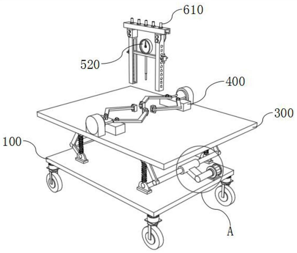
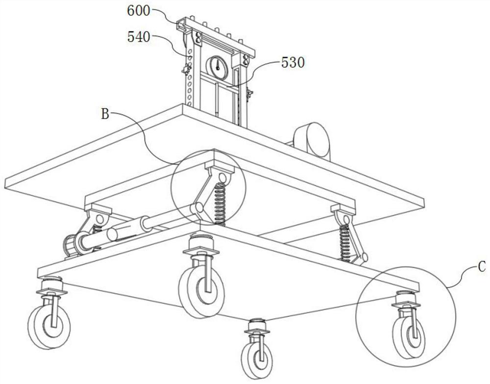
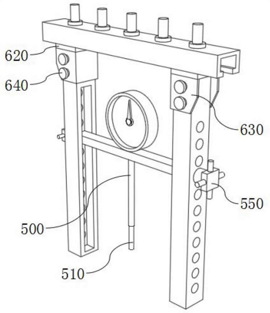
[0032] see Figure 1-7 As shown, the present invention is a vibration detection device manufactured by a mechanical arm, including a base 100, a drive mechanism 200, a vibration mechanism 300, a clamping mechanism 400, a detection mechanism 500 and a fixed frame 600, the base 100 includes a base body, and the drive mechanism 200 Including a driving mechanism body, a driving bar 230, a bearing tube 240 and a driving tube 250, the vibrating mechanism 300 includes a vibrating mechanism body, a first vibrating bar 320, a second fixed block 330 and a second vibrating bar 340, and the clamping mechanism 400 includes a clamping Mechanism body and clamping oil cylinder 410, detection mechanism 500 includes slide rail 540, fixed frame 600 includes clamping block 630 and clamping bolt 640, the lower surface of several driving mechanism bodies is welded with the upper surface of base body, and one end of two driving bars 230 is respectively It is welded to the side surfaces of two bearin...

Embodiment 2

[0040] see Figure 1-7 As shown, the present invention is a vibration detection device manufactured by a mechanical arm, wherein the model of the driving motor 210 is Y2-80M2-6, and the model of the clamping cylinder 410 is SC-DR40*20ST. 250 and the bearing tube 240 reduce the friction coefficient of the driving motor 210, increase the rotational power of the driving motor 210, speed up the vibration frequency, make the detection effect better, and can adjust the output efficiency of the driving motor 210 to control the vibration The frequency makes the detection control and adjustment more convenient. The first vibrating bar 320 and the second vibrating bar 340 convert the rotational motion brought by the drive tube 250 into a feed motion, thereby driving the vibrating mechanism body to vibrate, and the connecting spring 350 increases the stability. To prevent excessive vibration frequency from causing damage to the device, the clamping cylinder 410 pushes the piston rod 420 ...


PUM


Abstract

The invention discloses a vibration detection device for mechanical arm manufacturing, and relates to the technical field of mechanical arm manufacturing. The device comprises a base, a driving mechanism, a vibration mechanism, a clamping mechanism, a detection mechanism and a fixing frame, wherein the base comprises a base body, the lower surfaces of a plurality of driving mechanism bodies are welded to the upper surface of the base body, one ends of two driving strips are welded to the side surfaces of two bearing tubes respectively, one ends of a plurality of first vibration strips and oneends of a plurality of second vibration strips are welded to one ends of a plurality of driving pipes respectively, the lower surfaces of two clamping mechanism bodies and the lower surfaces of two clamping oil cylinders are welded to the upper surface of a vibration mechanism body, and one ends of two sliding rails are connected with one ends of two clamping blocks respectively. A sensor is arranged to convert vibration parameters of a mechanical arm into electric signals, the electric signals are amplified through an electronic circuit and then displayed through a reader, the position of a sliding strip on the sliding rails can be adjusted through adjusting bolts according to the dimension and size of the mechanical arm, and the operation is more convenient.

Description

technical field [0001] The invention belongs to the technical field of mechanical arm manufacturing, in particular to a vibration detection device for mechanical arm manufacturing. Background technique [0002] Vibration is a very common research problem in engineering applications. According to relevant data, more than 60% of vibration detection methods are used for equipment status detection and fault diagnosis. The accuracy of vibration detection equipment needs to be completed by calibration equipment. , the research on the vibration calibration instrument is particularly important. By installing the vibration acceleration signal sensor on the parts that can excite the vibration of the engine, the vibration of the test point must have a certain representativeness, which can accurately and stably reflect the excitation force and the vibration of the engine. Parameters such as vibration amplitude or frequency. [0003] Through market research, the technical team found tha...

Claims


Application Information

Patent Timeline
Patent Type & Authority Applications(China)
IPC IPC(8): B25J19/00
CPCB25J19/0095B25J19/007
Inventor 程卫清
Owner 程卫清
Why Eureka
Try Eureka