Temporary road structure and construction method thereof

A technology for temporary roads and construction methods, applied in infrastructure engineering, roads, roads, etc., can solve problems such as poor road smoothness, impermeable membrane puncture, deformation, etc., to achieve low environmental pollution hazards, avoid sinking or deformation, Good road smoothness

Pending Publication Date: 2021-03-09
CHINA RAILWAY NO 2 ENG GRP CO LTD +1
View PDF0 Cites 1 Cited by
  • Summary
  • Abstract
  • Description
  • Claims
  • Application Information

AI Technical Summary

Problems solved by technology

[0004] The purpose of the present invention is to solve the problem of easy puncture of the anti-seepage film, poor road surface smoothness, or long-term dynamic load caused by repeated rolling of vehicles in the existing temporary road built on the anti-seepage film of the garbage dump body in the prior art. To solve the problem of uneven settlement and deformation of garbage dumps, provide a temporary road structure and its construction method

Method used


Image

  • Temporary road structure and construction method thereof
  • Temporary road structure and construction method thereof

Examples


Embodiment 1

[0050] After more than 20 years of operation accumulation, the supporting facilities in a certain urban waste landfill are seriously aging, especially the water section of the original flood discharge tunnel is insufficient, and heavy rainfall will lead to HDPE laid on the surface of the waste dump in the landfill area. The rainwater on the anti-seepage membrane (hereinafter referred to as "anti-seepage membrane") cannot be discharged in time, and seeps down into the garbage dump, causing the garbage dump to slide; at the same time, the original flood discharge tunnel is equipped with leachate pipes, which have been exposed to rainwater for a long time. Scouring can easily cause damage to the pipeline, and it cannot be repaired in time when it rains, resulting in mixed flow of rain and sewage to pollute the environment. In order to realize the diversion of rainwater and sewage and ensure the safety of the landfill reservoir area, it is urgent to build a flood discharge tunnel s...

Embodiment 2

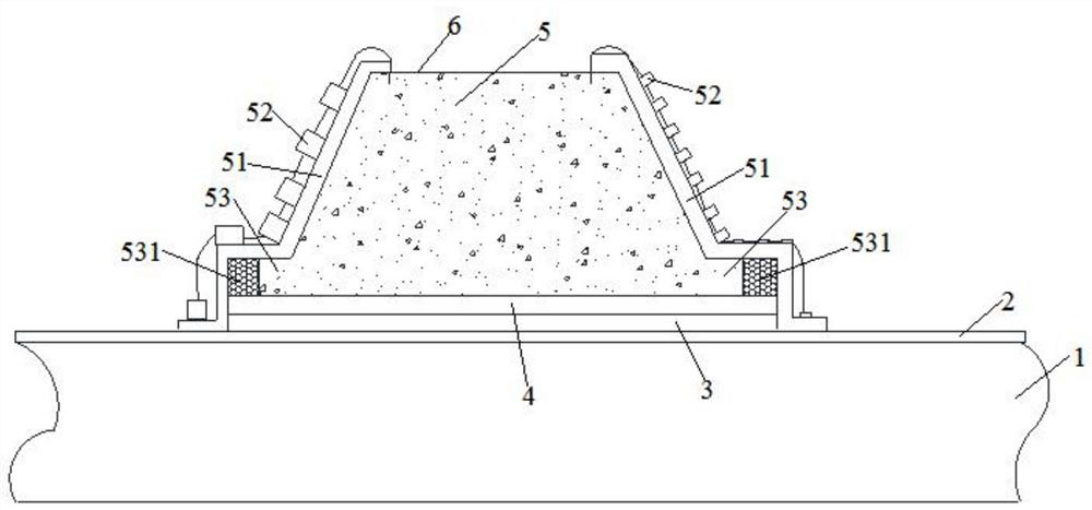
[0060] The construction method of the temporary road structure on the original anti-seepage membrane 2 of the garbage dump body 1 in embodiment 1 specifically comprises the following steps:

[0061] Step A: Carry out construction stakeout according to the horizontal direction of the road, sprinkle ash lines on the original anti-seepage membrane 2 of the garbage dump body 1 to mark the road construction scope.

[0062] Step B: Remove the presser foot sandbag on the surface of the original anti-seepage membrane 2 on the garbage dump body 1 within the construction scope. After the removal is completed, lay a new layer of the first anti-seepage membrane with a thickness of 2 mm on the surface of the original anti-seepage membrane 2 Layer 3, the first anti-seepage film layer 2 is a plurality of anti-seepage films spliced ​​together, and the adjacent two anti-seepage films are connected by hot-melt welding to form a whole, which plays a backup role for the original anti-seepage film....


PUM

PropertyMeasurementUnit
Thicknessaaaaaaaaaa
Thicknessaaaaaaaaaa
Permeability coefficientaaaaaaaaaa

Abstract

The invention relates to a temporary road structure and a construction method thereof. The temporary road structure is sequentially paved with a first impermeable film layer, a bentonite waterproof cushion layer and a roadbed body from bottom to top. Wherein the first impermeable film layer is paved above an original impermeable film layer of a garbage heap body; a pavement is arranged at the topend of the roadbed body; the temporary road structure can effectively prevent the impermeable film from being punctured, so that landfill gas and leachate in a garbage heap are prevented from leaking,and the overall stability of the garbage heap is prevented from being influenced; meanwhile, the pavement is good in flatness, the capacity of bearing vertical loads downwards transmitted by the pavement can be achieved in the temporary road period operation period, the loads are effectively diffused, and a garbage heap cannot sink or deform. The roadbed body and the road surface are of a mixed structure comprising soil and gravels.

Description

technical field [0001] The invention relates to the technical field of traffic road construction, in particular to a temporary road structure and a construction method thereof. Background technique [0002] In urban waste landfills, due to the aging of supporting equipment or the damage of leachate pipes in the original flood discharge tunnels, rainwater cannot be discharged when it rains, resulting in the slippage of garbage piles or the mixed flow of rain and sewage to pollute the environment. . When building a new flood discharge tunnel or performing on-site maintenance, in order to facilitate the transportation of personnel, materials, and equipment required for on-site construction, an anti-seepage membrane is required on the garbage dump (the anti-seepage membrane is a HDPE anti-seepage membrane laid on the surface of the garbage dump) On new temporary roads. [0003] At present, the following two methods are generally used to build temporary roads on the anti-seepag...

Claims


Application Information

Patent Timeline
IPC IPC(8): E01C3/00E01C3/06E01C9/08E02D17/20E02D31/00
CPCE01C3/00E01C3/06E01C9/08E02D17/20E02D17/202E02D31/006E02D2300/004E02D2450/106
Inventor 魏源陈平杨刚龙科模梁肖江尹培龚平李劲夫
Owner CHINA RAILWAY NO 2 ENG GRP CO LTD
Why Eureka
Try Eureka