
Quick positioning and connecting structure for steel plate shear wall in fabricated building

A technology of steel plate shear wall and connection structure, which is applied in building components, building structures, buildings, etc., can solve the deformation of steel plate shear wall and floor slab, reduce the connection stability of steel plate shear wall, and the local force load is large, etc. question

Inactive Publication Date: 2021-03-09
杨玮军
View PDF7 Cites 0 Cited by
  • Summary
  • Abstract
  • Description
  • Claims
  • Application Information

AI Technical Summary

Problems solved by technology

[0003] The existing steel plate shear wall positioning connection structure usually adopts the connection method of bolts and embedded clip joints, which makes the contact area between the steel plate shear wall and the floor slab larger, resulting in a larger local force load on the two. After time is connected, the deformation of the steel plate shear wall and the floor is prone to occur, which reduces the connection stability of the steel plate shear wall

Method used


Image

  • Quick positioning and connecting structure for steel plate shear wall in fabricated building
  • Quick positioning and connecting structure for steel plate shear wall in fabricated building
  • Quick positioning and connecting structure for steel plate shear wall in fabricated building

Examples


Embodiment Construction

[0036] The following will clearly and completely describe the technical solutions in the embodiments of the present invention with reference to the accompanying drawings in the embodiments of the present invention. Obviously, the described embodiments are only some, not all, embodiments of the present invention.

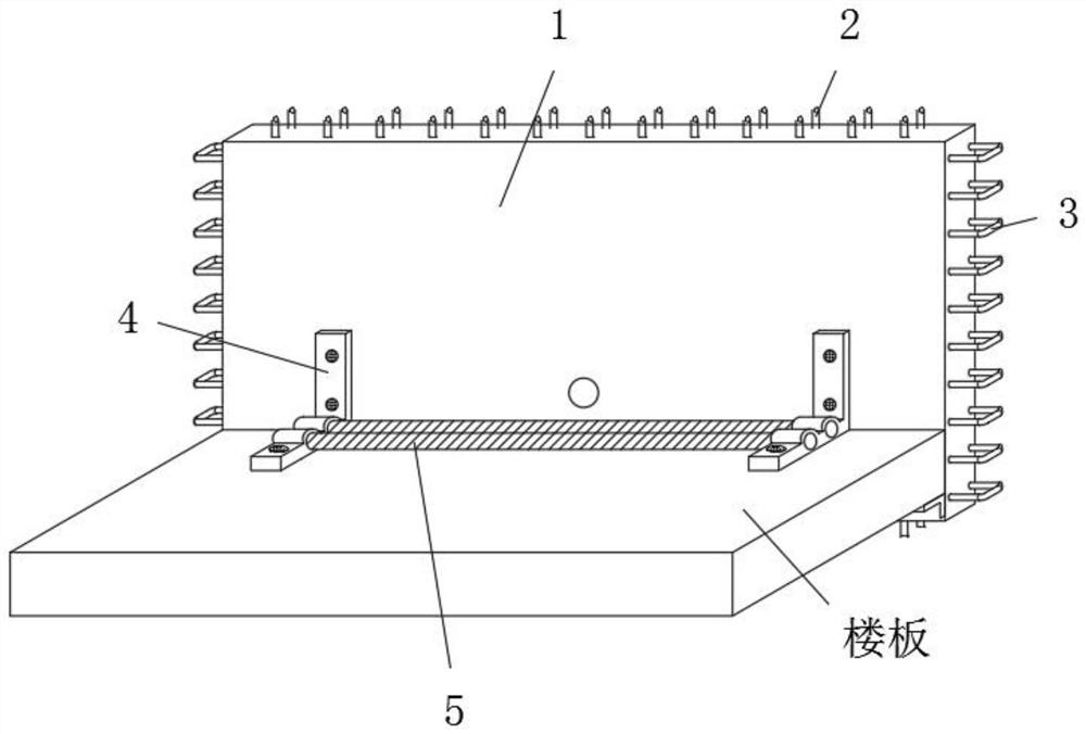
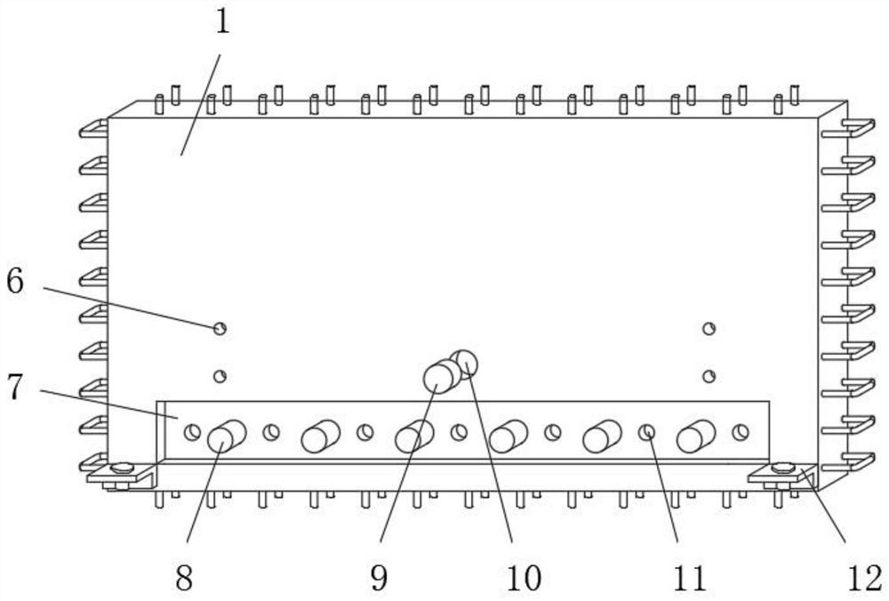
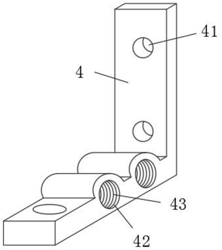
[0037] Such as Figure 1-Figure 3 As shown, a steel plate shear wall rapid positioning connection structure in a prefabricated building, including steel plate shear wall 1:

[0038] An assembly groove 7 is provided on the steel plate shear wall body 1, and the assembly groove 7 is correspondingly connected with the floor slab;

[0039] The two parallel sides of the steel plate shear wall 1 are pre-embedded with longitudinal reinforcement frames 2, and the other two parallel sides are pre-embedded with transverse reinforcement frames 3;

[0040] It also includes a reinforcing rib frame 4, the reinforcing rib frame 4 is provided with a positioning hole 41, and the pos...


PUM


Abstract

The invention discloses a quick positioning and connecting structure for a steel plate shear wall in a prefabricated building. The quick positioning and connecting structure involves a steel plate shear wall body provided with assembling grooves, wherein the assembling grooves are correspondingly connected with a floor slab; and the quick positioning and connecting structure further comprises reinforcing rib frames provided with positioning holes, the positioning holes are fixedly connected with positioning grooves in the steel plate shear wall body and the floor slab through penetrating positioning bolts correspondingly, limiting holes are formed in the horizontal ends of the reinforcing rib frames, and force bearing rods parallel to the floor slab are arranged in the limiting holes in apenetrating mode. According to the positioning and connecting structure, through the arranged reinforcing rib frames, the contact area of the joint of the steel plate shear wall body and the floor slab can be increased, so that the accurate positioning and connecting effects on the steel plate shear wall body is achieved, the reinforcing rib frames can be further reinforced and supported in combination with the supporting effect of the force bearing rods, the position stability of the reinforcing rib frames is ensured, and then the effect of rapid positioning and connecting of the steel plateshear wall is effectively achieved.

Description

technical field [0001] The invention relates to the technical field of prefabricated buildings, in particular to a fast positioning and connecting structure of a steel plate shear wall in a prefabricated building. Background technique [0002] Shear walls, also known as wind-resistant walls, seismic walls or structural walls, are walls in houses or structures that mainly bear horizontal loads and vertical loads caused by wind loads or earthquakes, to prevent structural shear damage, also known as seismic walls, generally Made of reinforced concrete, the shear wall is divided into plane shear wall and cylindrical shear wall. In order to increase the rigidity, strength and collapse resistance of the structure, some parts can be cast-in-place or prefabricated reinforced concrete shear wall, steel plate Due to its excellent strength, the shear wall has a wide range of use in prefabricated buildings. In order to ensure the maximum effect of the steel plate shear wall, it is neces...

Claims


Application Information

Patent Timeline
IPC IPC(8): E04B2/00E04B5/00E04B1/61E04B1/41
CPCE04B1/41E04B1/61E04B2/00E04B5/00E04B2001/6195
Inventor 杨玮军
Owner 杨玮军
Learn More