Efficient oil-gas separation device

A separation device, oil and gas technology, applied in the direction of engine components, machines/engines, mechanical equipment, etc., can solve the problem of poor effect of oil and gas separators, and achieve the effects of low manufacturing cost, easy disassembly and assembly, and high efficiency

Pending Publication Date: 2021-03-09
天津特瑞捷动力科技有限公司
View PDF0 Cites 1 Cited by
  • Summary
  • Abstract
  • Description
  • Claims
  • Application Information

AI Technical Summary

Problems solved by technology

[0008] Based on the above problems, the present disclosure provides a high-efficiency oil-gas separation device to alleviate technical problems such as the poor effect of the oil-gas separator in the prior art

Method used


Image

  • Efficient oil-gas separation device
  • Efficient oil-gas separation device
  • Efficient oil-gas separation device

Examples


Embodiment Construction

[0062]The disclosure provides a high-efficiency oil-gas separation device. The high-efficiency oil-gas separation device has high oil-gas separation efficiency and good separation effect, and meets the oil-gas separation requirements under various working conditions of the engine. The high-efficiency oil-gas separation device can be installed on various materials On the cylinder head shield, the installation space is small, easy to disassemble and assemble, and the manufacturing cost is low.

[0063] In order to make the purpose, technical solutions and advantages of the present disclosure clearer, the present disclosure will be further described in detail below in conjunction with specific embodiments and with reference to the accompanying drawings.

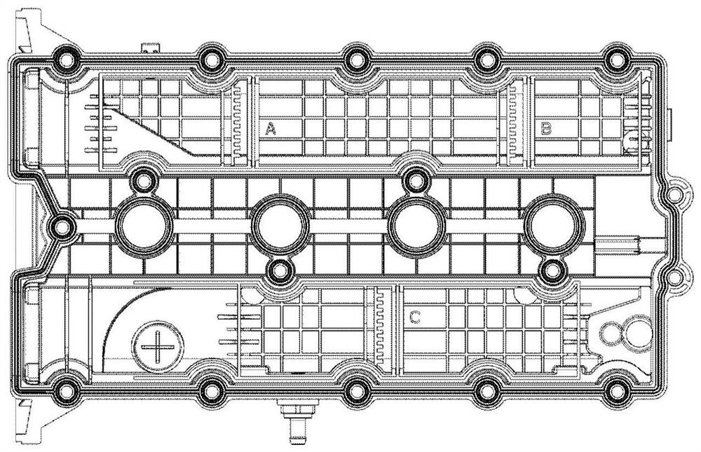
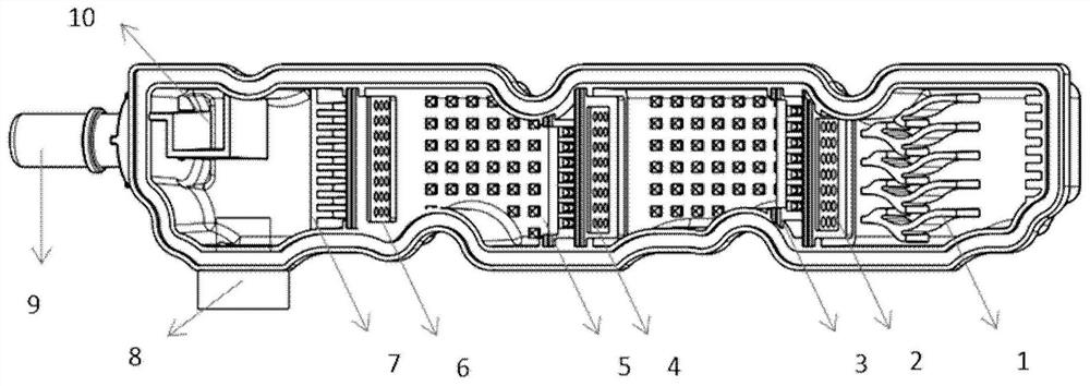
[0064] In an embodiment of the present disclosure, a high-efficiency oil-gas separation device is provided, such as image 3 and Figure 4 As shown, the high-efficiency oil-gas separation device includes: oil-gas separation str...


PUM


Abstract

The invention provides an efficient oil-gas separation device which comprises a coarse separation structure of a wave-shaped boss structure, a first-stage fine separation structure, a second-stage fine separation structure and a third-stage fine separation structure, wherein oil-gas mixed gas enters from a gas inlet, is partly cooled to be liquid through impact with the boss, and returns to an oilpan through a coarse filtering return port, the first-stage fine separation structure can separate oil drops in the oil-gas mixed gas, the oil drops return to the oil pan through a first-stage oil return port, the second-stage fine separation structure can separate oil drops in the oil-gas mixed gas, the oil drops return to the oil pan through the first-stage oil return port, the third-stage fineseparation structure can separate oil drops in the oil-gas mixed gas, the oil drops return to the oil pan through a second-stage oil return port, and the oil-gas mixed gas passes through the third-stage fine separation structure and then is discharged through a gas outlet.

Description

technical field [0001] The disclosure relates to the technical field of oil-gas separation, in particular to a high-efficiency oil-gas separation device. Background technique [0002] At present, when the engine is working, part of the combustible mixture and combustion products will pass through the piston ring and enter the crankcase from the cylinder. This part of the piston blow-by gas will carry part of the engine oil through the crankcase ventilation system and enter the cylinder for combustion. Separation from piston blow-by gas will cause the engine to "burn oil". [0003] There are existing solutions to the phenomenon of engine "burning oil" by using a cyclone oil-gas separator, such as figure 1 As shown, its working principle is: when the oil mist gas enters the cyclone separation tube in the axial direction, the air flow is strongly rotated by the guide vane, and the air flow spirals downward along the cylinder and enters the cyclone cylinder with high density. ...

Claims


Application Information

Patent Timeline
Patent Type & Authority Applications(China)
IPC IPC(8): F01M13/04F01M13/00
CPCF01M13/0405F01M2013/0072F01M2013/0411F01M2013/0427F01M2013/0433
Inventor 张辰张良超张增光傅豪杨冰丁光辉
Owner 天津特瑞捷动力科技有限公司
Why Eureka
Try Eureka