Universal transmission shaft for bearing

A universal transmission and transmission shaft technology, which is applied in the direction of couplings, elastic couplings, mechanical equipment, etc., can solve the problems of complex assembly of transmission shafts and connecting sleeves, difficult cost control, and large friction

Pending Publication Date: 2021-03-09
云模精密科技(东莞)有限公司
View PDF0 Cites 0 Cited by
  • Summary
  • Abstract
  • Description
  • Claims
  • Application Information

AI Technical Summary

Problems solved by technology

[0004] 1. The shaft sleeve and the connecting rod, the connecting rod and the connecting sleeve are all directly arranged hinged connections. During the actual use of the cardan shaft, especially when the steering angle is larger, the friction generated between the parts will increase. The bigger it is, the performance of the product will be affected;
[0005] 2. It is necessary to set up a corresponding structure at the end of the transmission shaft to supply the shaft sleeve and the connecting rod for installation. The assembly between the transmission shaft and the connecting sleeve is complicated and the force performance is high. The structure of the end of the transmission shaft is complex and the force High performance requirements, difficult to control costs

Method used


Image

  • Universal transmission shaft for bearing
  • Universal transmission shaft for bearing

Examples


Embodiment 1

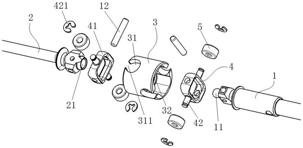
[0031] like figure 1 As shown, a bearing cardan shaft is provided in this embodiment, which mainly includes a first transmission shaft 1, a second transmission shaft 2 and a connecting sleeve 3, and the end of the first transmission shaft 1 connects from the connecting sleeve One end of the cylinder 3 is protruded and set, the end of the second transmission shaft 2 is protruded from the other end of the connecting sleeve 3, and the first transmission shaft 1 is protruded and set on the connecting sleeve 3 One end inside is in transmission connection with the end of the second transmission shaft 2 protruding into the connection sleeve 3; as one of the preferred solutions, the transmission connection here includes in the first transmission shaft 1 A sphere 11 is provided at the end, and a spherical concave surface 21 for the sphere 11 to embed is provided at the end of the second transmission shaft 2, and the sliding contact between the sphere 11 and the spherical concave surfac...

Embodiment 2

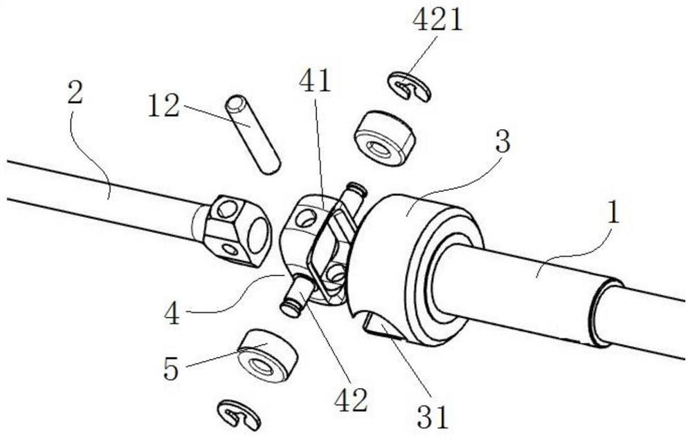
[0043] like figure 2 As shown, the similarities with Embodiment 1 will not be repeated; this embodiment provides another structural form of the bearing cardan shaft, mainly including the first transmission shaft 1, the second transmission shaft 2 and the connecting sleeve 3 .

[0044] The end of the first transmission shaft 1 and one end of the connecting sleeve 3 are in an integrated structure, and the end of the second transmission shaft 2 is protruded from the other end of the connecting sleeve 3. One end of the second transmission shaft 2 protruding into the connecting sleeve 3 is provided with the rotating connecting piece 4, and the connecting column 42 and the bearing are passed between the rotating connecting piece 4 and the connecting sleeve 3. The component 5 and the structural hole 31 form a transmission connection.


PUM


Abstract

The invention belongs to the technical field of transmission mechanisms, and particularly provides a universal transmission shaft for a bearing. The universal transmission shaft comprises a connectingsleeve, a first transmission shaft and a second transmission shaft, wherein the ends of the first transmission shaft and the second transmission shaft extend into the two ends of the connecting sleeve respectively, and the first transmission shaft and the second transmission shaft are in transmission connection; connecting columns are arranged on the first transmission shaft and/or the second transmission shaft, and structural holes corresponding to the connecting columns are formed in the connecting sleeve; and the connecting columns are rotatably connected with the structural holes by arranging bearing parts. According to the universal transmission shaft, in the using process, friction force between parts can be effectively reduced, a larger steering angle is obtained, and the using performance of a product is improved.

Description

technical field [0001] The invention belongs to the technical field of transmission mechanisms, and in particular relates to a bearing universal transmission shaft. Background technique [0002] As a transmission component, the cardan shaft is widely used in the automotive field. And especially for the model car, the cardan shaft in the traditional technology, the relative rotation between the drive shaft and the connecting sleeve is mostly realized by setting the connecting rod, and the other swinging motion of the drive shaft The realization, then will be set by the end of transmission shaft and between connecting rod, the axle sleeve that mutually matches is set. [0003] And existing this structural form, there is following shortcoming at least: [0004] 1. The shaft sleeve and the connecting rod, the connecting rod and the connecting sleeve are all directly set hinged connections. During the actual use of the cardan shaft, especially when the steering angle is larger,...

Claims


Application Information

Patent Timeline
Patent Type & Authority Applications(China)
IPC IPC(8): F16D3/221F16D3/84
CPCF16D3/221F16D3/84
Inventor 蒋春晓
Owner 云模精密科技(东莞)有限公司
Why Eureka
Try Eureka