Buffer device for quick switch

A buffer device and fast switch technology, applied in electrical switches, contact vibration/shock damping, vibration suppression adjustment, etc., can solve problems such as poor reliability and poor buffer performance, achieve small footprint, meet operating characteristics, drive Low process friction effect

Pending Publication Date: 2022-08-05
西安合容开关有限公司
View PDF0 Cites 0 Cited by
  • Summary
  • Abstract
  • Description
  • Claims
  • Application Information

AI Technical Summary

Problems solved by technology

[0003] The purpose of the present invention is to provide a buffer device for fast switching, which solves the problems of poor buffer performance and poor reliability of the existing buffer device

Method used


Image

  • Buffer device for quick switch
  • Buffer device for quick switch
  • Buffer device for quick switch

Examples


Embodiment Construction

[0019] The present invention will be described in detail below with reference to the accompanying drawings and specific embodiments.

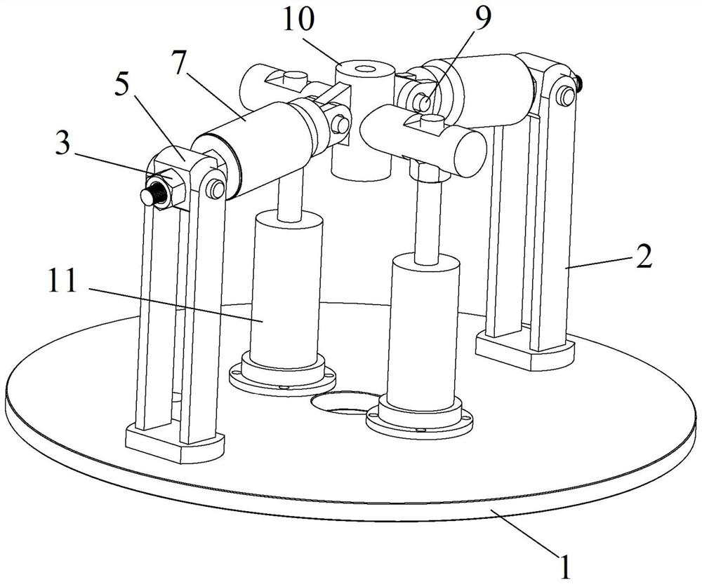
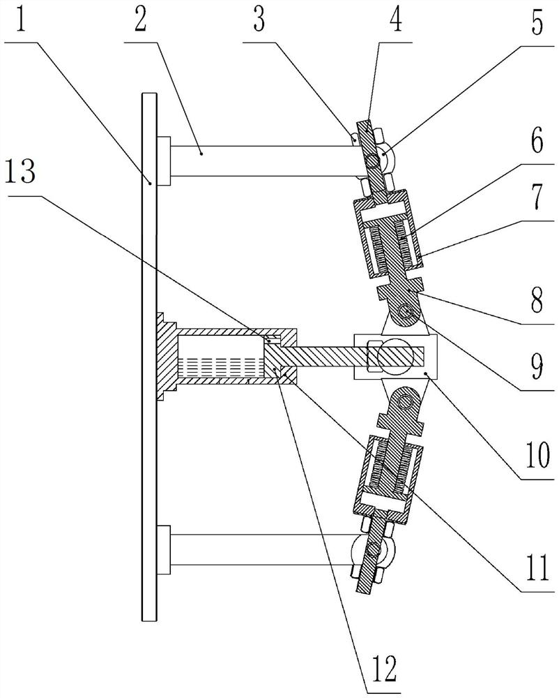
[0020] Cushioning devices for quick switches, such as Figure 1-2 As shown, it includes a support flange 1, one side of the support flange 1 is fixedly connected with the oppositely arranged holding brackets 2, and the ends of the two holding brackets 2 away from the support flange 1 are connected with a support rod seat 4, and the support rod seat 4. A disc spring sleeve 7 is fixedly connected to the end away from the holding bracket 2, and a compression spring rod 8 is sleeved in the disc spring sleeve 7;

[0021] It also includes a buffer structure, the buffer structure is fixed on one side of the support flange 1, the end of the buffer structure away from the support flange 1 is fixed with a cross drive shaft 10, and the opposite ends of the cross drive shaft 10 are respectively connected with the compression spring rod 8. end connection. ...


PUM


Abstract

The invention discloses a buffer device for a quick switch, which comprises a support flange, one side of the support flange is fixedly connected with oppositely arranged holding brackets, the end parts, far away from the support flange, of the two holding brackets are connected with support rod seats, the end parts, far away from the holding brackets, of the support rod seats are fixedly connected with disc spring sleeves, and pressure spring rods are sleeved in the disc spring sleeves; the buffer structure is fixedly connected to one side of the supporting flange, a cross-shaped transmission shaft is fixedly connected to the end, away from the supporting flange, of the buffer structure, and the two opposite ends of the cross-shaped transmission shaft are connected with the ends of the pressure spring rods respectively. The device is convenient to connect, simple in equipment debugging and mounting, small in friction force in the transmission process, novel in oil buffer structure, capable of meeting the action characteristic of a rapid switch, capable of keeping buffer integrated design, simple in overall structure, small in occupied space and small in transmission friction force of parts, and the service life of the equipment is greatly prolonged.

Description

technical field [0001] The invention belongs to the technical field of electrical buffering equipment, and particularly relates to a buffering device for a quick switch. Background technique [0002] As a new type of power equipment, the fast switch can realize the rapid cut-off in the first half-wave of the short-circuit current of the system. The electromagnetic repulsion mechanism used in the circuit breaker has a faster closing and opening speed than that of the conventional circuit breaker. Therefore, it needs a more reliable and better performance buffer mechanism, and the existing buffer device is seriously worn between the parts during use, which is very difficult. It is easy to get stuck, resulting in poor buffering effect. SUMMARY OF THE INVENTION [0003] The purpose of the present invention is to provide a buffer device for quick switch, which solves the problems of poor buffer performance and poor reliability of the existing buffer device. [0004] The techn...

Claims


Application Information

Patent Timeline
Patent Type & Authority Applications(China)
IPC IPC(8): F16F15/073F16F15/023H01H3/60H01H9/02
CPCF16F15/073F16F15/023F16F15/022H01H3/60H01H9/02
Inventor 刘盛张宇佳李国强滕保文肖丁月黄泽钰洪育凡蒋志刚卢伟飞呼延明张理隆唐园博王艺霖
Owner 西安合容开关有限公司
Why Eureka
Try Eureka