Electronically-controlled lifting-type multi-channel reversing ball valve

A reversing ball valve, lift-type technology, used in multi-way valves, valve details, valve devices, etc., can solve the problems of large valve space, inability to independently control, troublesome inspection and maintenance, etc., to reduce the opening and closing stroke and improve the transmission. The effect of stability and convenient later maintenance

Active Publication Date: 2021-10-22
JIANGSU EVALVE GRP
View PDF5 Cites 0 Cited by
  • Summary
  • Abstract
  • Description
  • Claims
  • Application Information

AI Technical Summary

Problems solved by technology

[0005] The technical problem to be solved by the present invention is: in order to solve the problems existing in the above-mentioned background technology, provide an improved multi-channel reversing ball valve with electronically controlled lifting type, which solves the problem that the current multi-channel ball valve will cause problems between different channels during the rotation of the ball. Mutual gas flow affects the sealing performance, and most of them are split valve bodies. Valves with the same pressure and caliber take up a lot of space, and the casting cost is relatively high. Moreover, the balls in different valve bodies can only rotate synchronously and cannot be controlled independently, which leads to later detection. Troublesome maintenance and inconvenient control

Method used


Image

  • Electronically-controlled lifting-type multi-channel reversing ball valve
  • Electronically-controlled lifting-type multi-channel reversing ball valve
  • Electronically-controlled lifting-type multi-channel reversing ball valve

Examples


Embodiment Construction

[0026] The present invention is described in further detail now in conjunction with accompanying drawing. These drawings are all simplified schematic diagrams, which only illustrate the basic structure of the present invention in a schematic manner, so they only show the configurations related to the present invention.

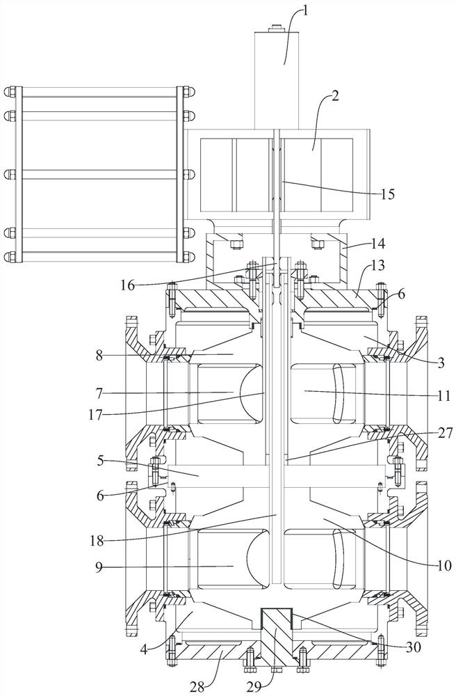
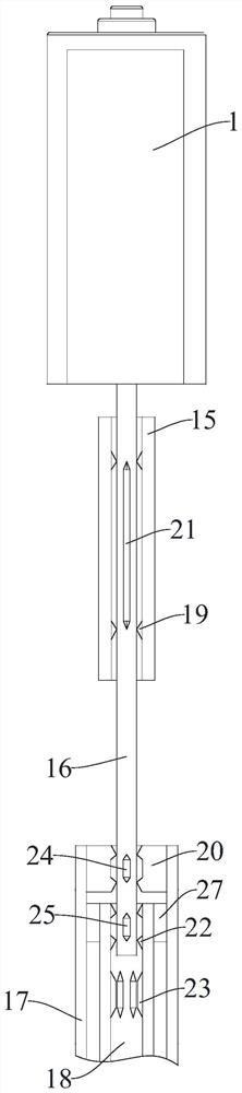
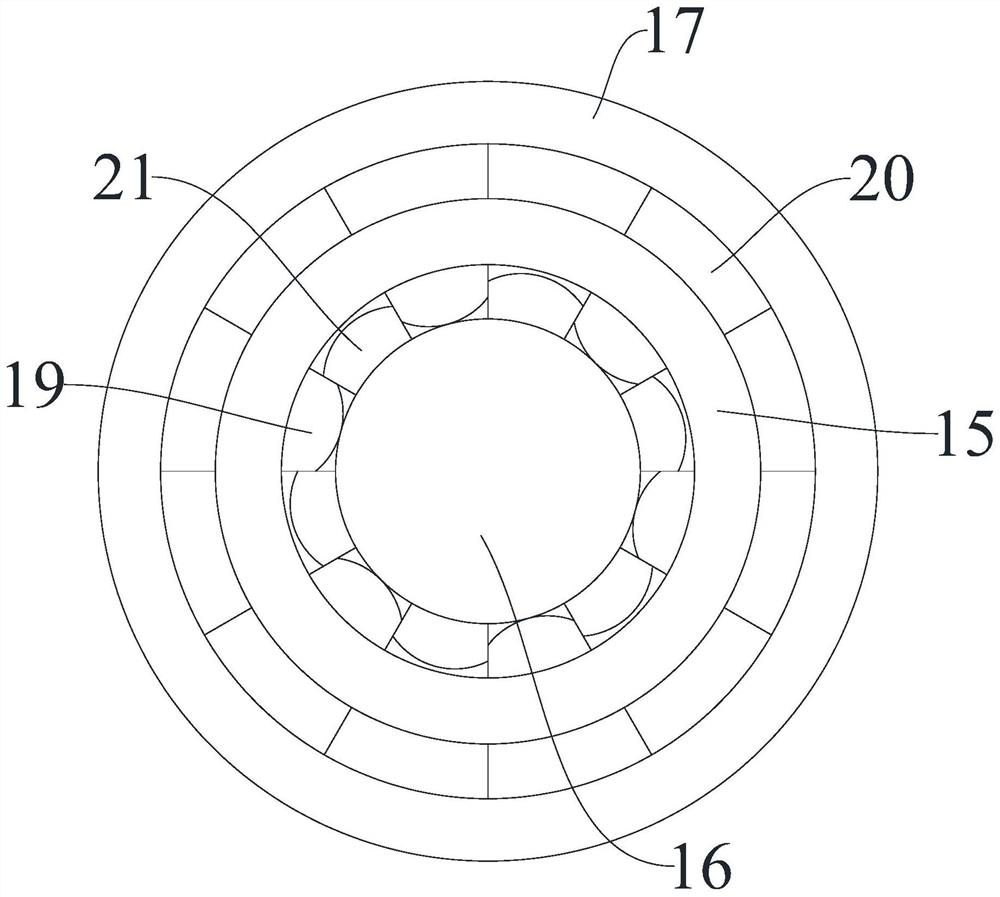
[0027] figure 1 , figure 2 and image 3 The one shown has an electronically controlled lifting multi-channel reversing ball valve, including a main valve body, an electric lifter 1 and a pneumatic actuator 2, and the main valve body includes an upper valve body 3, a lower valve body 4 and a middle isolation plate 5, The upper and lower ends of the upper valve body 3 and the upper and lower ends of the lower valve body 4 are provided with a loading and unloading opening with a built-in assembly sinker 6. The upper valve body 3 is equipped with an upper ball 8 with a built-in first four-channel 7. The lower valve body 4. The lower sphere 10 with the second f...


PUM


Abstract

The invention relates to the technical field of multi-channel sealing elements, in particular to an electronically-controlled lifting-type multi-channel reversing ball valve which comprises a main valve body, an electric lifter and a pneumatic actuator. According to the electronically-controlled lifting-type multi-channel reversing ball valve, the integrated structural design is adopted, a middle partition plate is fixed between an upper valve body and a lower valve body, streaming is avoided when the ball body rotates, and the sealing performance of an inner cavity of the whole ball valve is greatly improved; a communication end of a first four-way channel and a second four-way channel is fixedly connected with an inclined internal partition plate internally provided with an internal assembly pipe, so that the opening and closing stroke in the ball valve can be effectively reduced, and control is convenient; the connection relation among a longitudinal adjusting rod, a first extension control pipe and a second extension control pipe is switched and controlled through longitudinal adjustment, the internal ball body can be freely controlled according to needs, the operation modes are more diversified, and the application range is wider; the electric elevator can conveniently and rapidly control the driving relation between the pneumatic actuator and the upper ball body and the lower ball body, and the friction force produced in opening and closing is reduced.

Description

technical field [0001] The invention relates to the technical field of multi-channel seals, in particular to an electronically controlled lifting multi-channel reversing ball valve. Background technique [0002] Ball valves are widely used in petroleum refining, long-distance pipelines, chemical industry, papermaking, pharmaceuticals, water conservancy, electric power, municipal, steel and other industries, and occupy a pivotal position in the national economy. Ball valve and plug valve belong to the same type of valve, only its closing part is a sphere, and the sphere rotates around the centerline of the valve body to achieve opening and closing. The ball valve is mainly used to cut off, distribute and change the flow direction of the medium in the pipeline. It only needs to be rotated 90 degrees and a small rotational torque can be closed tightly. Ball valves are most suitable for on-off and shut-off valves. Ball valve is a new type of valve widely used. [0003] The wo...

Claims


Application Information

Patent Timeline
Patent Type & Authority Applications(China)
IPC IPC(8): F16K11/20F16K27/06
CPCF16K11/20F16K27/067
Inventor 钱玉峰沈圣华施晗张庆荣
Owner JIANGSU EVALVE GRP
Why Eureka
Try Eureka