Fluid switch, working method and application thereof
A technology of fluid switch and working method, which is applied in the direction of gas/liquid distribution and storage, valve device, pipeline system, etc., which can solve the problems of micro-flow insensitivity, inability to realize two-way flow detection, etc., so as to reduce processing difficulty and facilitate independent Easy adjustment, installation and maintenance
- Summary
- Abstract
- Description
- Claims
- Application Information
AI Technical Summary
Problems solved by technology
Method used
Image

Examples
specific Embodiment approach 1
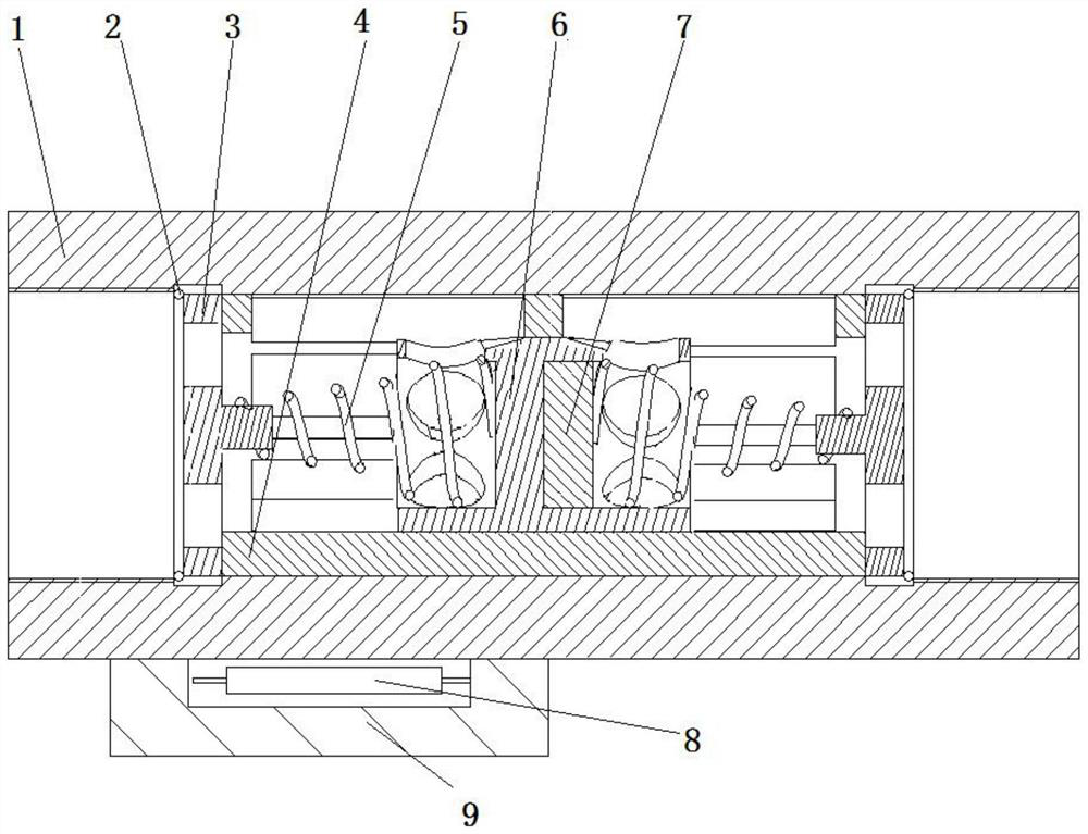
[0034] Specific implementation mode one: combine Figure 1-Figure 12 Describe this embodiment. A fluid switch of this embodiment includes a valve body 1, an inner circlip 2, a spring seat 3, a valve sleeve 4, a spring 5, a valve core 6, a permanent magnet 7 and a reed switch 8. The valve body 1 Valve sleeve 4 is installed inside, valve core 6 is installed inside valve sleeve 4, valve sleeve 4 is slidingly connected with valve core 6, valve core 6 is connected with permanent magnet 7, spring seat 3 is installed at both ends of valve sleeve 4, spring seat 3 It is connected with the valve core 6 through the spring 5, the spring seat 3 is connected with the valve body 1 through the inner circlip 2, and a dry reed switch 8 is installed on the outside of the valve body 1. A fluid switch is a switch triggered by magnetic induction, and the fluid The switch is installed on the fluid pipeline. When there is no liquid flowing in the pipeline, the reed switch 8 is disconnected, and its t...
specific Embodiment approach 2
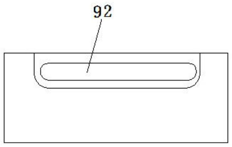
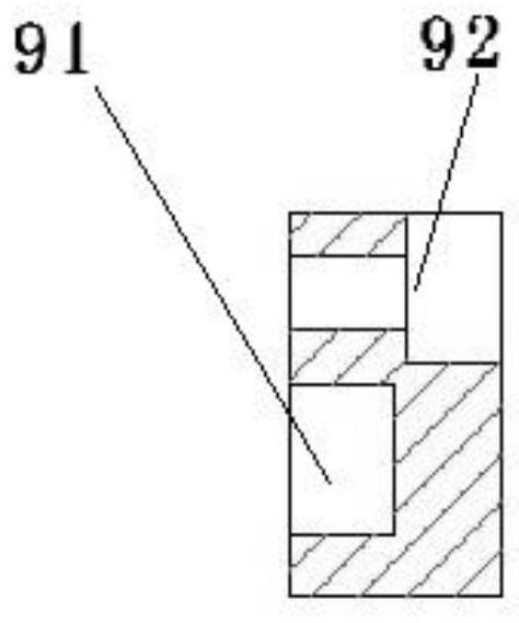
[0035] Specific implementation mode two: combination figure 1 , figure 2 , image 3 , Figure 7 , Figure 8 , Figure 9 Describe this embodiment, a fluid switch of this embodiment also includes a junction box 9, the junction box 9 has a reed switch installation groove 91 and an adjustment screw groove 92, and the reed switch 8 is installed in the reed switch installation groove 91 Inside, screw is installed in the adjusting screw groove 92 of junction box 9, and adjusting screw groove 92 is keyway shape, and screw is connected with sliding in adjusting screw groove 92, realizes the position adjustment of reed switch 8 by adjusting the position of junction box 9, adjusts After completion, tighten the screws to fix. The junction box 9 is connected to the valve body 1 by screws. The number of junction boxes 9 is two. The two junction boxes 9 are respectively arranged on both sides of the valve body 1. The valve body 1 is a regular hexagon. , the two junction boxes 9 are res...
specific Embodiment approach 3
[0036] Specific implementation mode three: combination figure 1 , Figure 10 , Figure 11 , Figure 12 This embodiment is described, a fluid switch of this embodiment, the spring 5 is a conical spring.
PUM
 Abstract
Description
Claims
Application Information
 - R&D
- Intellectual Property
- Life Sciences
- Materials
- Tech Scout
- Unparalleled Data Quality
- Higher Quality Content
- 60% Fewer Hallucinations
Browse by: Latest US Patents, China's latest patents, Technical Efficacy Thesaurus, Application Domain, Technology Topic, Popular Technical Reports.
© 2025 PatSnap. All rights reserved.Legal|Privacy policy|Modern Slavery Act Transparency Statement|Sitemap|About US| Contact US: help@patsnap.com