High-precision measuring device for silo test model interface pressure distribution and test method

A technology of pressure distribution and test model, applied in the direction of measuring device, using stable tension/pressure test material strength, force/torque/power measuring instrument, etc., can solve the problem of inconsistent interface stiffness, change of intergranular force distribution, and inability to reflect Problems such as contact force distribution state, to achieve the effect of eliminating force distribution and improving accuracy

Active Publication Date: 2021-03-09
NORTH CHINA INST OF SCI & TECH
View PDF14 Cites 1 Cited by
  • Summary
  • Abstract
  • Description
  • Claims
  • Application Information

AI Technical Summary

Problems solved by technology

Traditional pressure measurement needs to obtain the stress from the strain of the measuring instrument itself. The inconsistency of the interface stiffness caused by the deformation of this instrument will lead to changes in the boundary and internal intergranular force distribution of the particle system, which cannot reflect the initial contact force distribution state.
In addition, due to the size limitation of traditional measuring equipment, it is difficult to obtain sufficient force distribution data in small and medium-scale indoor experiments
Due to the limitations of the above-mentioned traditional testing methods, the silo tests conducted in the past mostly discussed the average value of the bottom pressure, and it was difficult to obtain sufficient data on the distribution of the pressure on the bottom surface

Method used


Image

  • High-precision measuring device for silo test model interface pressure distribution and test method
  • High-precision measuring device for silo test model interface pressure distribution and test method
  • High-precision measuring device for silo test model interface pressure distribution and test method

Examples


Embodiment Construction

[0029] In order to make the technical means, innovative features, goals and effects achieved by the present invention easy to understand, the present invention will be further described below.

[0030] The examples described here are specific specific implementations of the present invention, and are used to illustrate the concept of the present invention. They are all explanatory and exemplary, and should not be construed as limiting the implementation of the present invention and the scope of the present invention. In addition to the embodiments described here, those skilled in the art can also adopt other obvious technical solutions based on the claims of the application and the contents disclosed in the description, and these technical solutions include adopting any obvious changes made to the embodiments described here. Replacement and modified technical solutions.

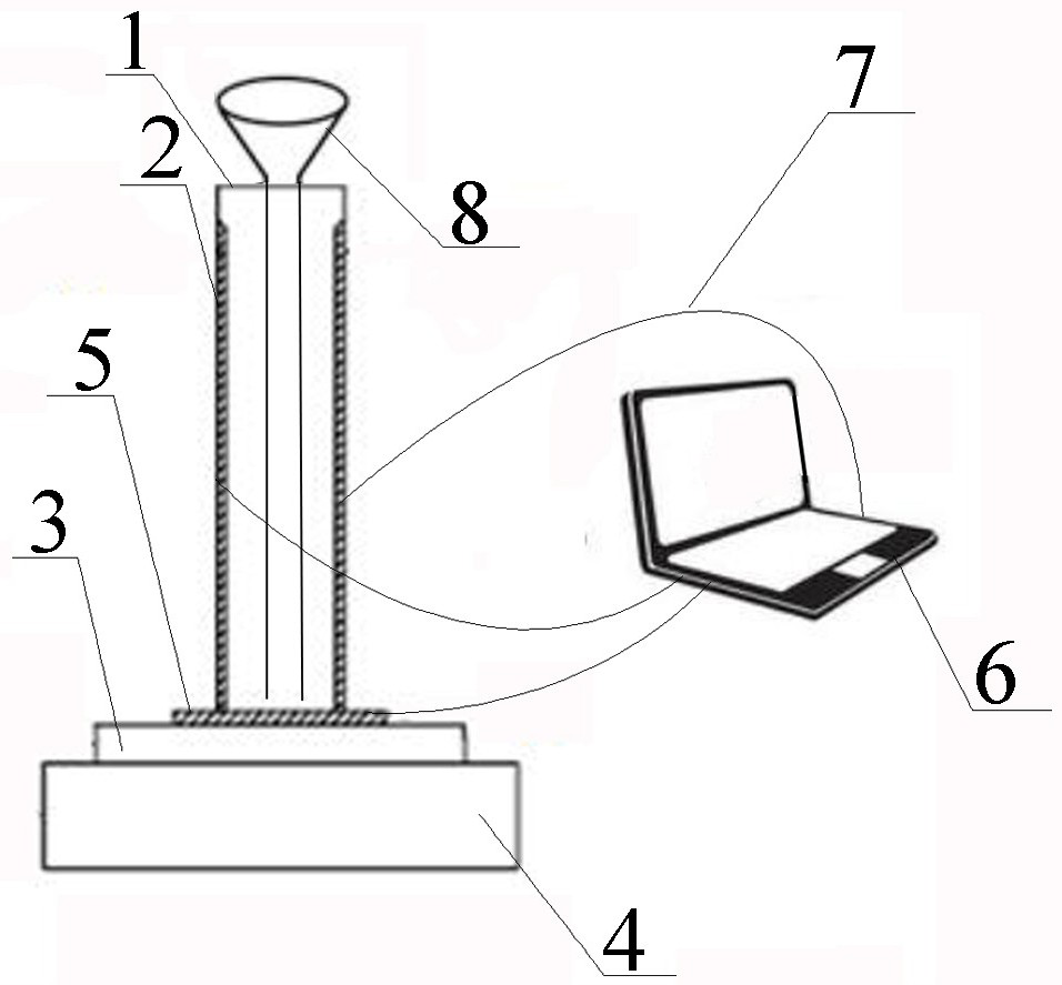
[0031] A high-precision measurement device for the interface pressure distribution of the silo test model,...


PUM

PropertyMeasurementUnit
heightaaaaaaaaaa

Abstract

The invention discloses a high-precision measuring device and a high-precision measuring method for silo test model interface pressure distribution. The high-precision measuring device comprises a silo container, a stress measuring device for particle column bottom/side wall pressure distribution in the silo container, and a feeding funnel; the silo container is of a hollow columnar structure madeof transparent materials, and the stress measuring device comprises strip-shaped flexible stress measuring films symmetrically laid on the inner wall of the silo container, a flexible stress measuring film block fixedly pressed at the bottom of the silo container, and a computer which is communicated with the strip-shaped flexible stress measuring film and the flexible stress measuring film blockthrough data lines. According to the invention, all cross sections including the outer wall of the silo container are arranged on the flexible stress measurement film block, so that a full-section high-density pressure distribution result can be obtained, and the change rule of pressure transmitted by the silo wall and the in-silo particle column can be compared and analyzed; the redistribution of internal force of a particle system caused by deformation of a traditional pressure test box is eliminated, and the silo pressure test accuracy is improved.

Description

technical field [0001] The invention relates to the field of indoor granular material testing, in particular to a high-precision measuring device and a testing method for interface pressure distribution of a silo testing model. Background technique [0002] "Silo effect" refers to the filling of granular materials inside the silo to form a granular column. As the height of the column increases, the pressure at the bottom of the granular column gradually tends to a certain saturation value, that is, the weight of the subsequently filled granular column. The transmission direction is deflected, no longer transmitted down to the bottom of the column, but gradually transmitted to the silo wall. [0003] Particulate materials widely exist in the field of engineering, fully understanding the engineering properties of granular materials has important physical and engineering practical significance. The engineering properties of granular materials are different from other cementiti...

Claims


Application Information

Patent Timeline
Patent Type & Authority Applications(China)
IPC IPC(8): G01N3/08G01N3/02G01L5/00
CPCG01N3/08G01N3/02G01L5/00G01L5/0028
Inventor 刘媛媛郭一辰宿绍波
Owner NORTH CHINA INST OF SCI & TECH
Why Eureka
Try Eureka