Welding joint expression method based on three-dimensional model

An expression method and 3D model technology, applied in the field of mechanical welding, can solve the problems of partially one-sided weld view expression, waste of paper and human resources, and a large number of drawing and printing operations, so as to achieve clear construction guidance, reduce deviation, and realize paperless The effect of modern design and construction

Active Publication Date: 2021-03-09
JIANGNAN SHIPYARD GRP CO LTD
View PDF5 Cites 4 Cited by
  • Summary
  • Abstract
  • Description
  • Claims
  • Application Information

AI Technical Summary

Problems solved by technology

The weld seam information in this way of expression is more complicated, and it needs to include many different weld seam information such as welding leg height, welding method, welding posture, current and voltage, etc., which is not clear and intuitive enough
In additi

Method used


Image

  • Welding joint expression method based on three-dimensional model
  • Welding joint expression method based on three-dimensional model
  • Welding joint expression method based on three-dimensional model

Examples


Embodiment Construction

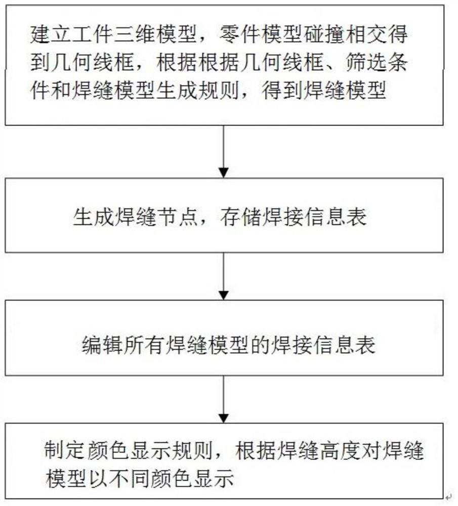
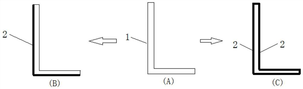
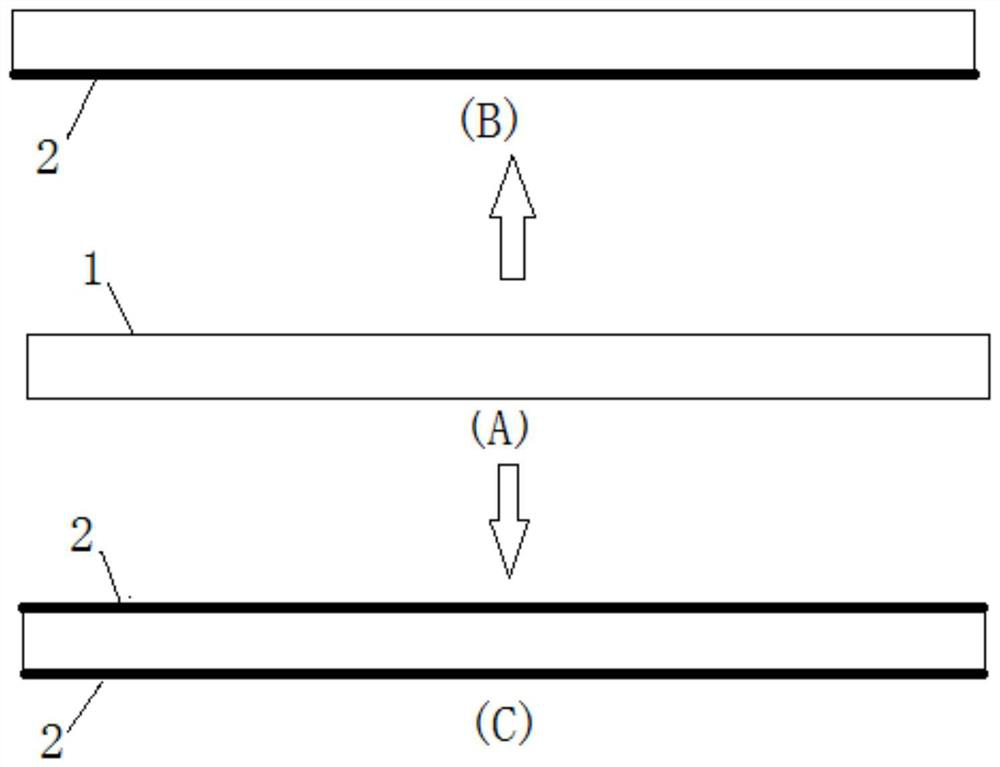
[0023] The implementation of the present invention will be illustrated by specific specific examples below, and those skilled in the art can easily understand other advantages and effects of the present invention from the contents disclosed in this specification.

[0024] It should be noted that the structures, proportions, sizes, etc. drawn in the drawings of this specification are only used to match the content disclosed in the specification, for those who are familiar with this technology to understand and read, and are not used to limit the conditions for the implementation of the present invention. Therefore, there is no technical substantive meaning, and any modification of structure, change of proportional relationship or adjustment of size shall still fall within the scope of the disclosure of the present invention without affecting the functions and objectives of the present invention. within the scope of technical content. At the same time, terms such as "upper", "lo...


PUM


Abstract

The invention relates to a weld joint expression method based o. The method is used for expressing information of weld joints among parts in a workpiece, and comprises the following steps of: S1, establishing a three-dimensional model of a workpiece in three-dimensional design software, and carrying out collision check on part models in the three-dimensional model to obtain a closed geometric wireframe; formulating a screening condition, and screening out a geometric wireframe needing to be calculated; formulating a weld joint model generation rule, and obtaining a weld joint model on a geometric wireframe needing to be calculated; S2, generating a weld joint node on each weld joint model, and storing a welding information table in each weld joint node, wherein the welding information tables at least comprise parameter items such as weld joint types, weld joint stages and weld joint lengths; S3, editing welding information tables of all the weld joint models, and determining numericalvalues or information of parameter items in the welding information tables; and S4, formulating a weld joint color display rule, classifying the weld joint models according to the weld leg heights ofthe weld joint models, and displaying the weld joint models by adopting different colors for different classifications.

Description

technical field [0001] The invention relates to the field of mechanical welding, in particular to a three-dimensional model-based welding seam expression method. Background technique [0002] In the production and construction process of ships, welding operations occupy an extremely important position, directly affecting the quality of ship construction. At present, in the shipbuilding industry, the quantity of welds is counted in the form of tables, and on-site construction personnel mainly carry out weld construction based on the weld information on the two-dimensional drawings. The weld seam information under this expression is more complicated, and needs to include many different weld seam information such as the height of the welding leg, welding method, welding posture, current and voltage, etc., which is not clear and intuitive enough. In addition, the weld seam view is relatively partial and one-sided, lacking an overall perspective, and prone to human errors. Fina...

Claims


Application Information

Patent Timeline
IPC IPC(8): G06F30/17G06T17/00
CPCG06F30/17G06T17/00
Inventor 李博林朱明华王健李海波王尧孙浩月
Owner JIANGNAN SHIPYARD GRP CO LTD
Why Eureka
Try Eureka