
Integral mounting structure of built-in mutual inductor for gas-insulated switchgear

A technology of overall installation and transformer, which is applied to the installation/support/suspension of inductors, transformers/reactors, and switchgear settings, etc., to simplify the construction steps, reduce the difficulty of construction and installation, and save installation time.

Pending Publication Date: 2021-03-09
SHANGHAI PINGGAO TIANLING SWITCHGEAR CO LTD +2
View PDF4 Cites 0 Cited by
  • Summary
  • Abstract
  • Description
  • Claims
  • Application Information

AI Technical Summary

Problems solved by technology

[0005] The technical problem to be solved by the present invention is to provide an overall installation structure of a built-in transformer for an inflatable cabinet in view of the above-mentioned shortcomings of the existing built-in voltage transformer or built-in current transformer installation structure. Mode, effectively reducing construction time, unifying standard construction actions, ensuring the accuracy of transformer secondary wiring, ensuring the safety of construction personnel, improving work efficiency, reducing construction difficulty, and reducing construction labor costs

Method used


Image

  • Integral mounting structure of built-in mutual inductor for gas-insulated switchgear
  • Integral mounting structure of built-in mutual inductor for gas-insulated switchgear
  • Integral mounting structure of built-in mutual inductor for gas-insulated switchgear

Examples


Embodiment Construction

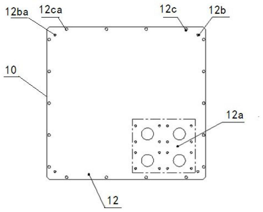
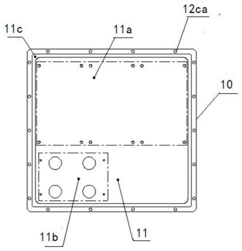
[0027] The present invention will be further described below in conjunction with the accompanying drawings and specific embodiments.

[0028] See attached Figure 1 to Figure 8 , shown in the figure is an embodiment of the overall installation structure of the built-in transformer for the inflatable cabinet. The overall installation structure of the built-in transformer for the inflatable cabinet in this embodiment includes three metal flange mounting plates 10, A, B, and C. The built-in transformer 20, the secondary sealing connector 30, the secondary metal baffle plate 70, the lifting ring 40, the flange plate sealing ring 50, the gas box 60 of the gas charging cabinet, and some fixing bolts of various specifications are used for the gas filling cabinet.

[0029] Such as Figure 1 to Figure 3 As shown, the metal flange mounting plate 10 includes an inner mounting surface 11 and an outer mounting surface 12 . The inner mounting surface 11 includes: a three-phase built-in tr...


PUM


Abstract

The invention discloses an integral mounting structure of a built-in mutual inductor for a gas-insulated switchgear. The integral mounting structure comprises a metal flange mounting plate, and a built-in mutual inductor fixedly mounted on the metal flange mounting plate. During the mounting, firstly, the built-in mutual inductor is mounted on the metal flange mounting plate to form an integral mounting module of the built-in mutual inductor, then the integral mounting module of the built-in mutual inductor is mounted on the gas-insulated switchgear, the built-in mutual inductor is arranged ina gas tank of the gas-insulated switchgear, the metal flange mounting plate is fixedly connected with the tank wall of the gas tank of the gas-insulated switchgear in a sealed mode, and a secondary connecting wire of the built-in mutual inductor is led out from the metal flange mounting plate. By changing the direct mounting structure of the built-in mutual inductor for the gas-insulated switchgear, all related mounting steps of the built-in mutual inductor are completed outside the gas-insulated switchgear, the mounting process of the built-in mutual inductor is standardized, the construction steps are simplified, the construction mounting difficulty is reduced, modular mounting of the built-in mutual inductor outside the gas-insulated switchgear is formed, and finally, the standard mounting structure is integrally hoisted.

Description

technical field [0001] The invention relates to the field of medium-voltage gas-insulated switchgear, in particular to an overall installation structure of a built-in transformer for an inflatable cabinet. Background technique [0002] Medium-voltage gas-insulated switchgear has the characteristics of high reliability, maintenance-free, and small footprint (compared to air cabinets). In the inflatable cabinet substation project, multiple inflatable cabinets are arranged in a group in the form of a combination of cabinets in the direction of the main bus. In a group of inflatable cabinets, isolation cabinets and some incoming cabinets will be installed with built-in voltage transformers or built-in current transformers for metering protection. The built-in voltage transformer or built-in current transformer appears in the form of three phases A, B, and C on each inflatable cabinet, and a certain phase distance is maintained between the two phases. The three-phase built-in vo...

Claims


Application Information

Patent Timeline
IPC IPC(8): H01F38/20H01F27/06H01F27/29H02B1/04H02B13/035
CPCH01F27/06H01F27/29H01F38/20H02B1/04H02B13/035
Inventor 柏海丰周玉华曹叶飞吴波王陆一李闯
Owner SHANGHAI PINGGAO TIANLING SWITCHGEAR CO LTD
Learn More