
Mechanical time-delay wall switch

A wall switch, mechanical technology, applied in the direction of switches with two operating positions, flip switches/rocker switches, etc., can solve the problems affecting the convenience of people traveling at night, single function, etc. performance, improving usability

Inactive Publication Date: 2021-03-09
李佳
View PDF0 Cites 0 Cited by
  • Summary
  • Abstract
  • Description
  • Claims
  • Application Information

AI Technical Summary

Problems solved by technology

The switches currently used have a simple structure and a single function, and there is no delay in turning off the lighting equipment, which seriously affects the convenience of people traveling at night

Method used


Image

  • Mechanical time-delay wall switch
  • Mechanical time-delay wall switch
  • Mechanical time-delay wall switch

Examples


Embodiment Construction

[0014] The technical solutions in the embodiments of the present invention will be clearly and completely described below in conjunction with the accompanying drawings in the embodiments of the present invention.

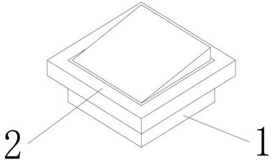
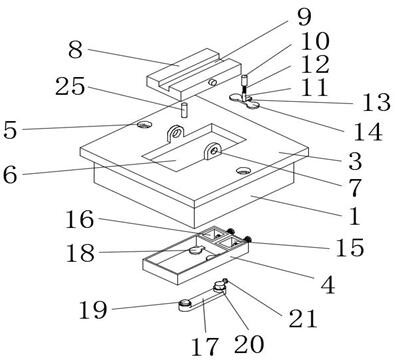
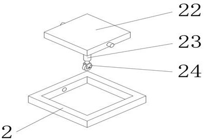
[0015] like Figure 1-3 As shown, a mechanical time-delay wall switch includes a main body 1 and a panel 2. The main body 1 is provided with a docking board 3 and a wiring module 4. The docking board 3 is installed and fixed on the top of the main body 1 by screws, and the docking board 3 is provided with The counterbore 5 and the through groove 6, the counterbore 5 is opened on both sides of the docking plate 3, the through groove 6 is opened in the middle of the butt plate 3, the two sides of the through groove 6 are integrally formed and connected with a U-shaped seat 7, and the wiring module 4 is integrally formed and connected to the In the middle of the main body 1, the panel 2 is buckled on the top of the docking plate 3, and the inner side of the U-shaped se...


PUM


Abstract

The invention discloses a mechanical time-delay wall switch which comprises a main body and a panel, the main body is provided with a butt joint plate and a wiring module, the butt joint plate is installed and fixed at the top of the main body through screws, the butt joint plate is provided with counter bores and a through groove, the counter bores are formed in the two sides of the butt joint plate, and the through groove is formed in the middle of the butt joint plate. U-shaped bases are integrally formed and connected to the two sides of the through groove, the wiring module is integrallyformed and connected to the middle of the interior of the main body, and the panel is buckled to the top of the butt joint plate. According to the invention, time-delay turn-off can be easily carriedout on an electric appliance or lighting equipment, and the practicability of the switch is effectively improved.

Description

technical field [0001] The invention relates to a mechanical time-delay wall switch, which belongs to the technical field of switches. Background technique [0002] A switch is an electronic component that can open a circuit, interrupt the current flow, or allow it to flow to other circuits. The currently used switch has simple structure and single function, and there is no delay when turning off the lighting equipment, which seriously affects the convenience of people traveling at night. In order to solve the above problems, a new technical solution is provided. Contents of the invention [0003] The purpose of the present invention is to provide a mechanical time-delay wall switch to solve the problems raised in the above-mentioned background technology. [0004] In order to achieve the above object, the present invention adopts the following technical solutions: a mechanical time-delay wall switch, including a main body and a panel, the main body is provided with a do...

Claims


Application Information

Patent Timeline
IPC IPC(8): H01H23/22H01H23/24
CPCH01H23/22H01H23/24
Inventor 李佳
Owner 李佳
Learn More