Defrosting heater and refrigerator provided with defrosting heater

A technology of defrosting heaters and heaters, which is applied in the field of cold storage, can solve problems such as the decline of heat passing rate, and achieve the effect of inhibiting corrosion and disconnection

Active Publication Date: 2021-03-09
PANASONIC INTELLECTUAL PROPERTY MANAGEMENT CO LTD
View PDF14 Cites 0 Cited by
  • Summary
  • Abstract
  • Description
  • Claims
  • Application Information

AI Technical Summary

Problems solved by technology

As a result, the heat passage rate dec

Method used


Image

  • Defrosting heater and refrigerator provided with defrosting heater
  • Defrosting heater and refrigerator provided with defrosting heater
  • Defrosting heater and refrigerator provided with defrosting heater

Examples


no. 1 Embodiment approach

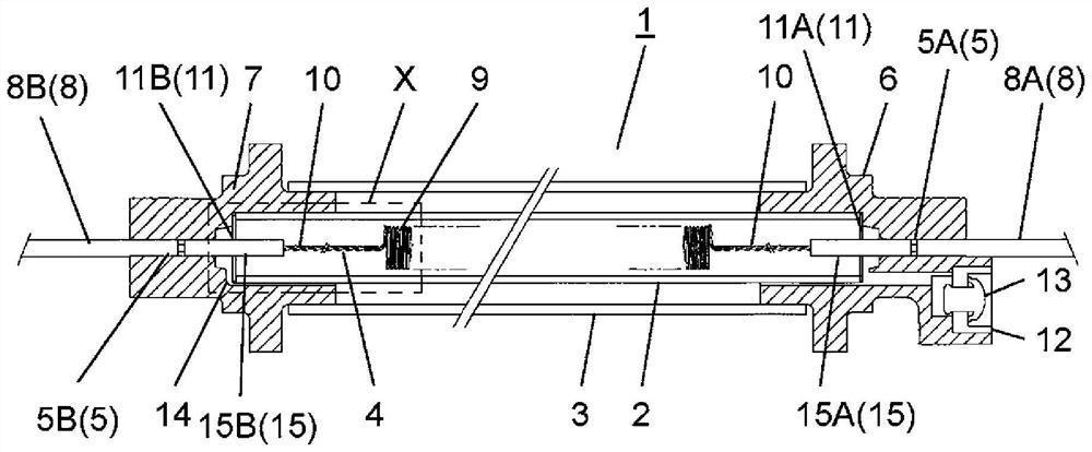
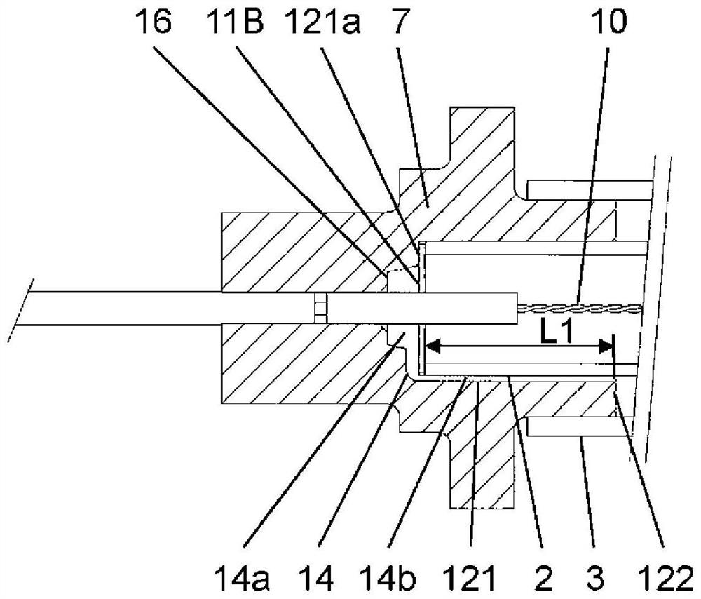
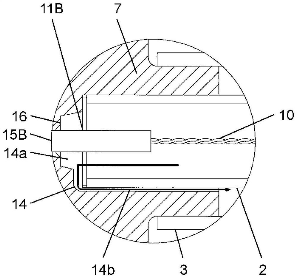
[0059] use Figure 1 to Figure 4 , Figure 7 and Figure 8 The figure of FIG. 1 illustrates the first embodiment of the present invention.

[0060] Such as figure 1 As shown, the defrost heater 1 includes a first glass tube 2, a second glass tube 3 arranged to cover the outer periphery of the first glass tube 2, and a metal resistor formed inside the first glass tube 2. Heater wire4.

[0061] The defrosting heater 1 includes a first plug 6 covering the opening of one end of both ends of the first glass tube 2 and the second glass tube 3 and a second plug 7 covering the opening of the other end. .

[0062] Lead wire insertion holes 5 are formed in the first plug 6 and the second plug 7 , respectively. In the two wire insertion holes 5 , the first wire insertion hole 5A is set in the first plug 6 , and the second wire insertion hole 5B is set in the second plug 7 . Here, the first lead wire insertion hole 5A and the second lead wire insertion hole 5B are collectively ref...

no. 2 Embodiment approach

[0135] use Figure 5 and Figure 6 , and the defrosting heater in the second embodiment of the present invention will be described.

[0136] In addition, the same code|symbol is attached|subjected to the same structure as 1st Embodiment, and detailed description is abbreviate|omitted.

[0137] In the first embodiment, the structure in which one passage 14 is provided in the second plug 7 has been described.

[0138] Also in this embodiment, no valve is provided on the second plug 207 . Such as Figure 5 As shown, the second plug 207 has the function of making the gas in the inner space of the first glass tube 2 flow to the outer peripheral surface of the first glass tube 2, the inner peripheral surface of the second glass tube 3, the first plug (not shown) and the second plug. The two plugs 207 form the passage 114 for the outflow of the space. That is, the passage 114 is provided on the side of the second plug 207 where no valve is provided.

[0139] The second plug 207...


PUM

PropertyMeasurementUnit
Cross-sectional areaaaaaaaaaaa
Lengthaaaaaaaaaa
Outer diameteraaaaaaaaaa

Abstract

A defrosting heater (1) is provided with: a first glass pipe (2); a second glass pipe (3); a heater wire (4); a first plug (6) that covers an end opening part provided at one ends of the first glass pipe (2) and the second glass pipe (3); and a second plug (7) that covers an end opening part provided at the other ends of the first glass pipe (2) and the second glass pipe (3). Only the first plug (6) has a valve (13) configured to flow the air in an internal space of the first glass pipe (2) and the air in a space formed by an outer peripheral surface of the first glass pipe (2), an inner peripheral surface of the second glass pipe (3), the first plug (6), and the second plug (7) to the outside. The second plug (7) has a path (14) that is configured to flow the air in the internal space ofthe first glass pipe (2) to a space formed by the outer peripheral surface of the first glass pipe (2), the inner peripheral surface of the second glass pipe (3), the first plug (6), and the second plug (7).

Description

technical field [0001] The present invention relates to a defrost heater for defrosting frost attached to or accumulated on an evaporator of a refrigeration cycle such as a refrigerator, and a refrigerator provided with the defrost heater. Background technique [0002] As an example of a defrosting heater such as a refrigerator, there is a glass tube heater (for example, refer to Patent Document 1). [0003] Below, based on Figure 9 , illustrating the structure of the existing defrosting heater. [0004] Figure 9 It is a main part sectional view of the conventional refrigerator 161. [0005] Freezer compartment 162 is disposed at the lowermost portion of refrigerator 161 . Freezer door 163 is provided on the front surface of freezer compartment 162 . Refrigerating room 164 is arranged above freezing room 162 . Refrigerating compartment door 165 is provided on the front surface of refrigerating compartment 164 . [0006] A cooler 166 , a glass tube heater 167 arranged ...

Claims


Application Information

Patent Timeline
IPC IPC(8): F25D21/08H05B3/06H05B3/44
CPCH05B3/06F25D21/08H05B3/44
Inventor 前田利树
Owner PANASONIC INTELLECTUAL PROPERTY MANAGEMENT CO LTD
Why Eureka
Try Eureka