
Fryer with rotatable frying cage

A frying pan and rotating shaft technology, which is applied to utensils for frying things in oil, household utensils, applications, etc., can solve the problems of reducing the use cycle of edible oil, falling food residues, and inability to flip, etc., to reduce stickiness. Attached to the outer wall of the baffle mechanism and the inner wall of the frying basket to prevent and reduce the effect of hot frying

Inactive Publication Date: 2021-03-12
董修茂
View PDF1 Cites 0 Cited by
  • Summary
  • Abstract
  • Description
  • Claims
  • Application Information

AI Technical Summary

Problems solved by technology

The fryer with this structure has the following disadvantages: the amount of oil used is large, and a large amount of edible oil needs to be added to the body of the fryer to make the oil surface exceed the food in the frying basket, otherwise the food on the surface of the frying basket will not be cooked; The frying effect is poor, and the food cannot be turned during the soaking and frying process, causing the food to become lumpy and not soft, and the taste and color are different. The bottom food is hard and browned, and the top food is soft and white.
[0003] In order to solve the above-mentioned problems, Chinese patent CN201010204746.6 discloses a kind of fried fryer with good food frying effect, no slots on both sides of the inner pot, saving cooking oil, and a rotatable frying cage for easy cleaning. In the process, some food materials will float on the oil surface after entering the oil pan. The rotating process cannot drive the food to rotate, and it is easier to cause food residues to fall during the rotating process. Food residues have been fried in the oil for a long time at high temperature. , make edible oil black, reduce the use cycle of edible oil

Method used


Image

  • Fryer with rotatable frying cage
  • Fryer with rotatable frying cage
  • Fryer with rotatable frying cage

Examples


Embodiment Construction

[0026] The following will clearly and completely describe the technical solutions in the embodiments of the present invention with reference to the accompanying drawings in the embodiments of the present invention. Obviously, the described embodiments are only some, not all, embodiments of the present invention.

[0027] Examples of the described embodiments are shown in the drawings, wherein like or similar reference numerals designate like or similar elements or elements having the same or similar functions throughout. The embodiments described below by referring to the figures are exemplary and are intended to explain the present invention and should not be construed as limiting the present invention.

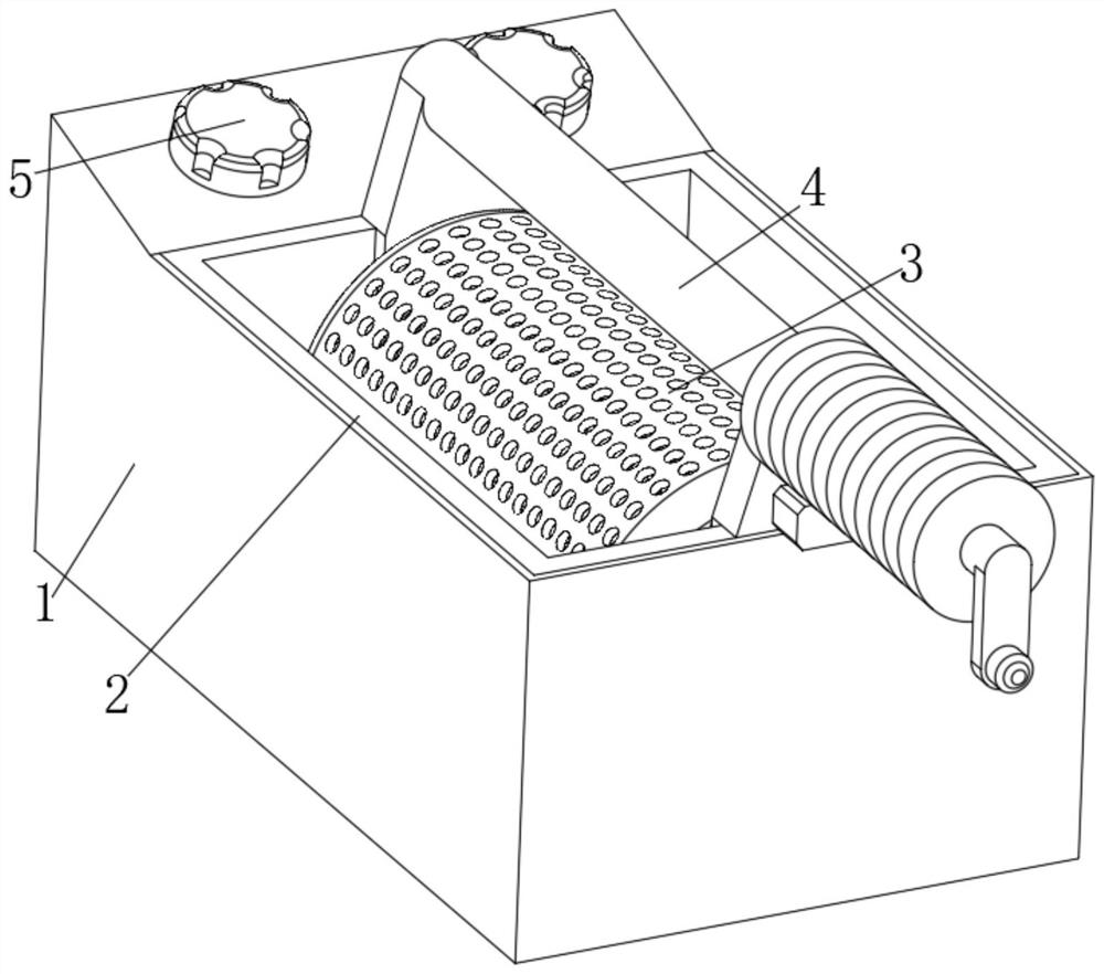
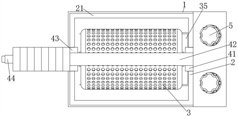
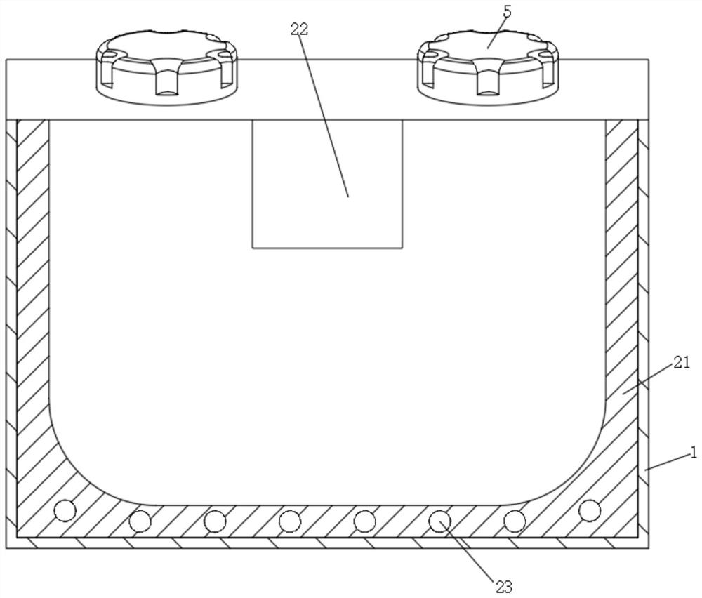
[0028] see Figure 1-7 , the present invention provides a technical solution: a fryer with a rotatable frying cage, including a temperature-insulating protective shell 1, the inner wall of the temperature-insulating protective shell 1 is movably connected with a heating mech...


PUM


Abstract

The invention discloses a fryer with a rotatable frying cage and relates to the technical field of fryer devices. The fryer with the rotatable frying cage comprises a heat insulation protection shell,wherein a heating mechanism is movably connected to the inner wall of the heat insulation protection shell, a frying cage mechanism is movably connected to the position, close to the center, in the heating mechanism, and the outer wall of the frying cage mechanism is movably connected with the inner wall of the heat insulation protection shell through the inner wall of the arranged heating mechanism; a positioning rotating mechanism is movably connected to the position, close to the top end, of the outer wall of the cage frying mechanism. According to the fryer with the rotatable frying cage,food floating on the oil liquid level can be driven by the outer wall of the baffle mechanism to rotate, the food is evenly heated, residues falling from the food can fall into the waste collecting box along the outer wall of the baffle mechanism, the situation that the residues are burnt by hot frying is reduced, and therefore the situation that edible oil becomes black can be avoided; The fryeris convenient to use.

Description

technical field [0001] The invention relates to the technical field of fryer devices, in particular to a fryer with a rotatable fryer basket. Background technique [0002] Currently known fryers generally include a loam cake, a frying basket and a pot body. The fryer basket with an open upper end is placed in the pot body, and the loam cake is placed above the pot body to cover the pot body and the frying basket. The fryer with this structure has the following disadvantages: the amount of oil used is large, and a large amount of edible oil needs to be added to the body of the fryer to make the oil surface exceed the food in the frying basket, otherwise the food on the surface of the frying basket will not be cooked; The frying effect is poor, and the food cannot be turned during the soaking and frying process, resulting in the food being lumpy and not soft, and the taste and color are different. The bottom food is hard and brown, and the top food is soft and white. [0003]...

Claims


Application Information

Patent Timeline
Patent Type & Authority Applications(China)
IPC IPC(8): A47J37/12
CPCA47J37/12A47J37/1276A47J37/129
Inventor 董修茂
Owner 董修茂
Learn More