

Turning plate sorting machine, turning plate sorting system, sorting method of turning plate sorting machine and supporting guide rail
A technology for supporting guide rails and sorting machines. It is applied in the field of supporting guide rails and flap sorters. It can solve problems such as no way to transport, affecting the realization of sorting, and tilting of cargo brackets.
- Summary
- Abstract
- Description
- Claims
- Application Information
AI Technical Summary
Problems solved by technology
Method used
Image


Examples
Embodiment 1
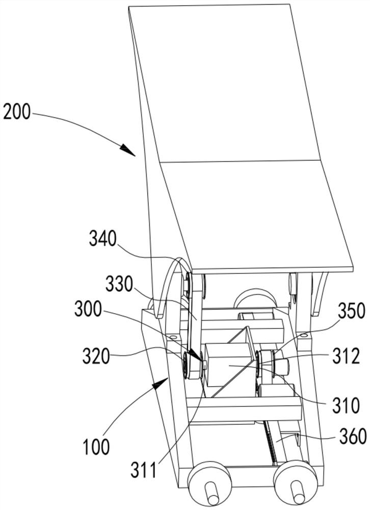
[0055] The flip sorting trolley disclosed by the present invention will be described below in conjunction with the accompanying drawings, as shown in the attached figure 1 As shown, it includes a vehicle frame 100 on which a stage 200 can be rotatably arranged relative to it, and a drive mechanism 300 for driving the stage 200 to rotate is arranged on the vehicle frame 100, and the drive mechanism 300 makes the carrier 200 in the attached Figure 5 Toggle between the three states shown,
[0056] In the first state, the carrier 200 is straightened, that is, both ends of the carrier 200 are at the same height;
[0057] In the second state, the stage 200 is inclined to the left, that is, the left end of the stage 200 is lower than the right end;
[0058] In the third state, the stage 200 is inclined to the right, that is, the left end of the stage 200 is higher than the right end.
[0059] During the sorting process, the drive mechanism 300 enables the carrier 200 to perform m...
Embodiment 2
[0070] This scheme further reveals a kind of flap sorter, as attached Figure 5 As shown, it includes the panel sorting trolley 400 of the above embodiment and a moving mechanism that drives the sorting trolley 400 to move. The number of the flip sorting trolley 400 can be designed according to needs, for example, in one mode, the number of the flip sorting trolley 400 can be only one, at this time, the moving mechanism can be a The device for turning the sorting cart 400 between two points can be, for example, an air cylinder, a hydraulic cylinder, or an electric cylinder.
[0071] In the preferred way, as attached Figure 5 As shown, the flap sorting trolleys 400 are multiple and distributed in a ring, and they are driven by the loop drive mechanism 500 to rotate along the ring formed by them. The shape formed by the flap sorting carts 400 is preferably waist-shaped Of course, other shapes are also possible.
[0072] The axis of the ring formed by the flap sorting trolley...
Embodiment 3
[0091] This scheme further reveals a kind of flap sorting system, as attached Figure 11 As shown, the above-mentioned flap sorter 1 is included, and the flap sorter 1 is also connected with a bag supply device 2, and the bag supply device 2 can be known with weighing, code scanning, measuring volume and For the DWS conveying line with conveying function, the specific setting position of the bag supply device can be adjusted according to the layout form of the flap sorter, for example, as shown in the attached Figure 11 As shown, when the flap sorter 1 is vertically arranged, that is, when the axis of the loop of the flap sorting trolley is horizontal, the bag supply device 2 is arranged at one end of the upper layer of the flap sorter place. as attached Figure 12As shown, when the flap sorter 1 is arranged horizontally, that is, when the axis of the loop of the flap sorting trolley is vertical, the bag supply device 2 can be arranged at the any position. as attached F...
PUM
 Abstract
Description
Claims
Application Information