Plate correcting system

A correction system and plate technology, applied in the direction of stamping machines, presses, manufacturing tools, etc., can solve the problems of high number of times of piston rod expansion and contraction, slow frequency of cylinder expansion and expansion, poor correction effect, etc., and achieve good pressing effect

Inactive Publication Date: 2021-03-12
HUNAN JONOVA AUTOMOBILE VEHICLES
View PDF0 Cites 0 Cited by
  • Summary
  • Abstract
  • Description
  • Claims
  • Application Information

AI Technical Summary

Problems solved by technology

[0002] Most of the existing plate correction systems use the cylinder to drive the pressure plate to press the plate to be pressed. In this way, the expansion and contraction frequency of the cylinder is slow, and the correction effect is poor. At the same time, the piston rod of the cylinder has more expansion and contraction times, which makes its service life shorter.

Method used


Image

  • Plate correcting system

Examples


Embodiment Construction

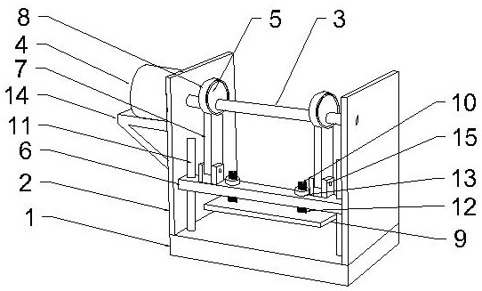
[0010] Below in conjunction with all accompanying drawings the present invention will be further described, and preferred embodiment of the present invention is: see appended figure 1 , a plate correction system described in this embodiment includes a base 1, side plates 2 are vertically fixed on the top of both sides of the base 1, and a rotating shaft 3 is movably installed between the upper parts of the two side plates 2, and one of the side plates 2 A rotating motor 4 is installed on the outer wall, and a motor mount 14 is fixed on the outer wall of one of the side plates 2 , and the rotating motor 4 is installed on the top of the motor mount 14 . The transmission shaft of the rotating motor 4 passes through the side plate 2 and is connected to the rotating shaft 3. An eccentric wheel 5 is fixedly installed on the rotating shaft 3. A lifting plate 6 is arranged below the rotating shaft 3. A lifting arm 7 is hinged on the top of the lifting plate 6. The lifting plate 6. A h...


PUM


Abstract

The invention provides a plate correcting system which comprises a base. Side plates are vertically fixed to the tops of the two sides of the base, a rotating shaft is movably installed between the upper portions of the two side plates, an eccentric wheel is fixedly installed on the rotating shaft, a lifting plate is arranged below the rotating shaft, a pressing plate is arranged below the liftingplate, and a buffer shaft is vertically fixed to the top of the pressing plate; a threaded section is arranged on the upper portion of the buffer shaft and upwards penetrates through the lifting plate to be connected with an adjusting nut in a meshed manner, the the buffer shaft between the pressing plate and the lifting plate is sleeved with a buffer spring, the top of the sleeved buffer springabuts against the bottom of the lifting plate, and the bottom of the buffer spring abuts against the top of the pressing plate; and a pressing area is reserved between the bottom of the installed pressing plate and the top of the base. According to the plate correcting system, by adopting the eccentric wheel, the pressing plate can press a to-be-pressed plate at high frequency, so that the pressing effect is good.

Description

technical field [0001] The invention relates to the technical field of plates, in particular to a plate correction system. Background technique [0002] Most of the existing plate correction systems use the cylinder to drive the pressure plate to press the plate to be pressed. In this way, the frequency of expansion and contraction of the cylinder is slow, and the correction effect is poor. At the same time, the piston rod of the cylinder expands and contracts more times, resulting in a shorter service life. Contents of the invention [0003] The purpose of the present invention is to overcome the deficiencies of the prior art, and provide a plate correction system with good pressing effect. [0004] In order to achieve the above purpose, the technical solution provided by the present invention is: a plate correction system, which includes a base, side plates are vertically fixed on the top of both sides of the base, and a rotating shaft is movably installed between the up...

Claims


Application Information

Patent Timeline
Patent Type & Authority Applications(China)
IPC IPC(8): B21D1/00B30B1/26
CPCB21D1/00B30B1/261
Inventor 李汉雄丁朝辉
Owner HUNAN JONOVA AUTOMOBILE VEHICLES
Why Eureka
Try Eureka