Conveying device for plate conveying of punching machine

A technology of conveying device and punching machine, applied in the field of punching machine, can solve the problems of high accident rate, high cost, few production parts, etc., and achieve the effect of avoiding danger, increasing stability and avoiding elimination.

Inactive Publication Date: 2021-03-12
陆天祥
View PDF0 Cites 0 Cited by
  • Summary
  • Abstract
  • Description
  • Claims
  • Application Information

AI Technical Summary

Problems solved by technology

[0003] The traditional punching machine is manually fed. The accident rate of manual feeding is very high, and the efficiency is unstable. The punching equipment cannot be used in conjunction. There are often too many parts produced in the previous process, which leads to the accumulation of parts, or the production of parts in the previous process. Too little, can't supply the post-process, some small enterprises want to replace the automatic feeding equipment, integrated punching machine, need to eliminate the existing equipment, the cost is high, and the use of the existing equipment will be lost
[0004] In view of the fact that the stamping machine in the related art cannot automatically feed materials, there is danger, and the cost of replacing equipment is high, so far no effective solution has been proposed

Method used


Image

  • Conveying device for plate conveying of punching machine
  • Conveying device for plate conveying of punching machine
  • Conveying device for plate conveying of punching machine

Examples


Embodiment Construction

[0024] The following will clearly and completely describe the technical solutions in the embodiments of the present invention with reference to the accompanying drawings in the embodiments of the present invention. Obviously, the described embodiments are only some, not all, embodiments of the present invention. All other embodiments obtained by persons of ordinary skill in the art based on the embodiments of the present invention belong to the protection scope of the present invention.

[0025] According to an embodiment of the present invention, a numerically controlled machining head using a plate-shaped machining head fixing device is provided, such as Figure 1 to Figure 7 As shown, among them,

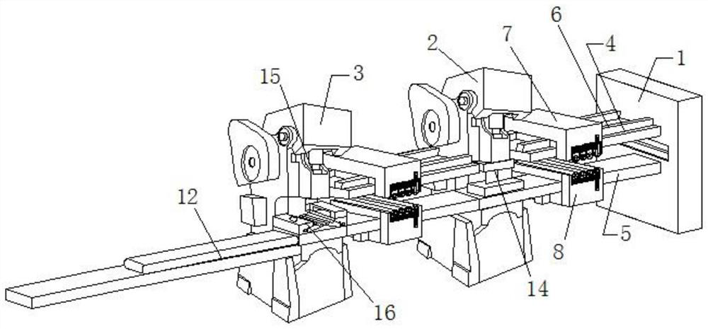
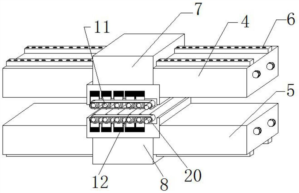
[0026]A conveying device for feeding plates of a punching machine, comprising a fixed table 1, a guide rail plate 1 4 and a guide rail plate 2 5 are fixedly installed between the fixed table 1 and the punching machine 2, the punching machine 2 and the punching machine 2 3 are al...


PUM


Abstract

The invention discloses a conveying device for plate conveying of a punching machine. The conveying device comprises a fixed table, a first guide rail plate and a second guide rail plate are fixedly installed between the fixed table and a first punching machine, a first guide rail plate and a second guide rail plate are fixedly installed between the first punching machine and a second punching machine, the first guide rail plate and the second guide rail plate are each provided with a plurality of servo sliding rails, a first sliding press-fit block is movably installed on the first guide railplate through the servo sliding rails, a second sliding press-fit block is movably installed on the second guide rail plate through the servo sliding rails, a plurality of elastic bases are arrangedat the bottom of the first sliding press-fit block, a plurality of elastic bases are arranged at the top of the second sliding press-fit block, bearing pedestals are fixedly installed on the elastic bases, conveying rollers are movably installed on the bearing pedestals, and a cam is fixedly installed at one end of each of the conveying rollers. According to the conveying device, machines are additionally installed on original equipment, the cost is low, linkage is generated between pieces of equipment, the production efficiency is improved, and the safety is improved.

Description

technical field [0001] The invention relates to the field of punching machines, in particular to a conveying device for feeding boards of the punching machine. Background technique [0002] A punch press is a stamping press. In national production, the stamping process has the advantages of saving materials and energy, high efficiency, low technical requirements for operators, and the ability to produce products that cannot be achieved by mechanical processing through various mold applications. Its use is more and more extensive. [0003] The traditional punching machine is manually fed. The accident rate of manual feeding is very high, and the efficiency is unstable. The punching equipment cannot be used in conjunction. There are often too many parts produced in the previous process, which leads to the accumulation of parts, or the production of parts in the previous process. Too little, can't supply the post-process, some small enterprises want to replace the automatic f...

Claims


Application Information

Patent Timeline
IPC IPC(8): B21D43/09B21D43/22B21D43/18B21D28/02B21D28/04B21D45/02
CPCB21D28/02B21D28/04B21D43/09B21D43/18B21D43/22B21D45/02
Inventor 不公告发明人
Owner 陆天祥
Why Eureka
Try Eureka