Herringbone gear centering degree on-line measurement and correction method

A herringbone gear and centering technology, which is applied in the direction of measuring/indicating equipment, gear tooth manufacturing devices, belts/chains/gears, etc., can solve the problem that the medium error of the herringbone gear is difficult to guarantee, the assembly process is time-consuming, and affects the grinding of teeth Processing accuracy and other issues to achieve the effect of improving processing accuracy, avoiding measurement errors, and facilitating motion correction

Pending Publication Date: 2021-03-12
NANJING UNIV OF TECH +1
View PDF13 Cites 5 Cited by
  • Summary
  • Abstract
  • Description
  • Claims
  • Application Information

AI Technical Summary

Problems solved by technology

When processing with a finger milling cutter (rod cutter), the moderate error is mainly controlled by scribing the knife, due to the error in the scribing, and the superimposition of errors generated during the heat treatment of the tooth surface and the finishing process in the subsequent processing , which makes it difficult to guarantee the moderate error of herringbone gears; when processing helical gears separately, it is necessary to determine the installation angle, workpiece axis and other factors through detection means to meet the requirements of the centering error, and the assembly process is time-consuming, and the assembly accuracy will directly affect Subsequent grinding precision

Method used


Image

  • Herringbone gear centering degree on-line measurement and correction method
  • Herringbone gear centering degree on-line measurement and correction method
  • Herringbone gear centering degree on-line measurement and correction method

Examples


Embodiment Construction

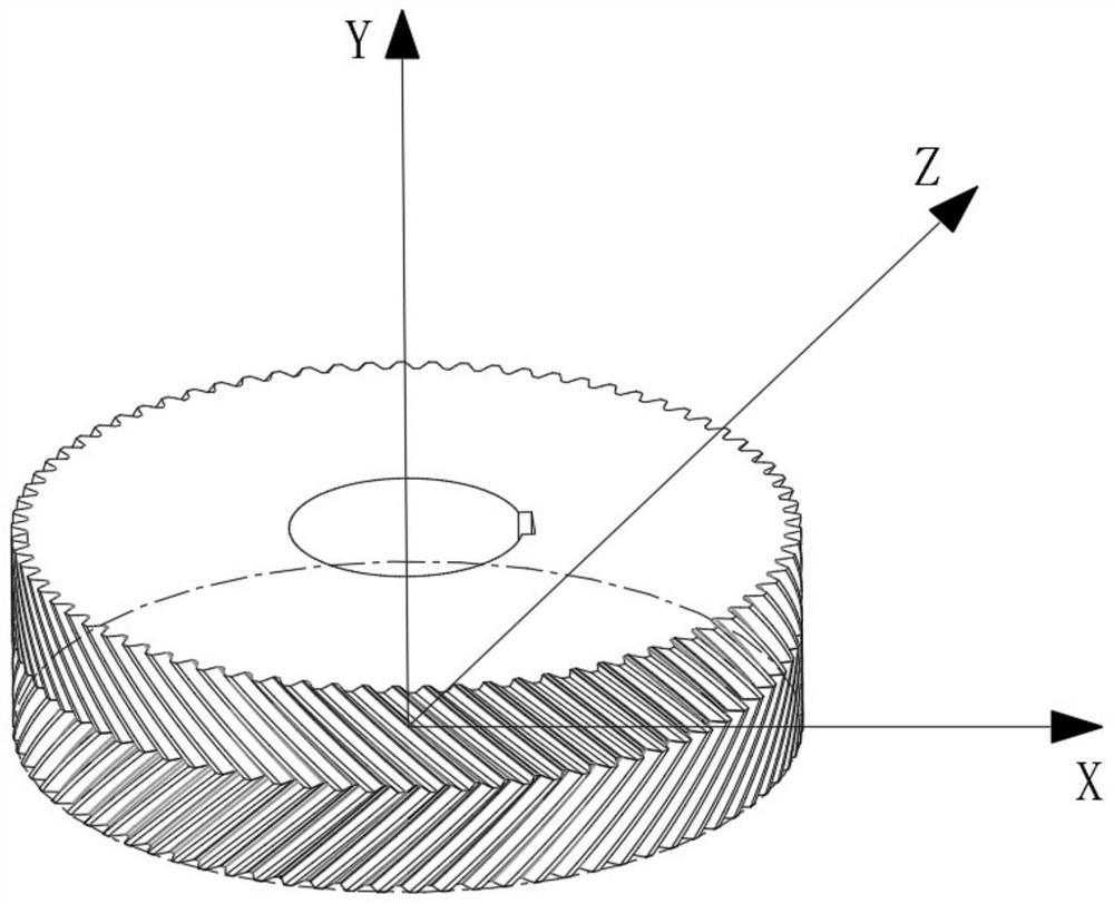
[0020] The following will combine Figure 1 to Figure 3 To illustrate this embodiment, the specific steps of a method for online measurement and correction of a herringbone gear alignment moderate error described in this embodiment are as follows:

[0021] Herringbone gear related parameters, such as figure 1 Shown: gear module: 12, number of teeth: 78, tooth pressure angle 20°, tooth helix angle 14°.

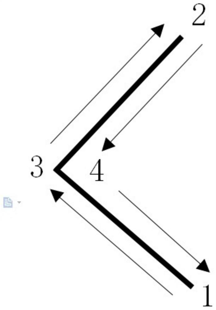
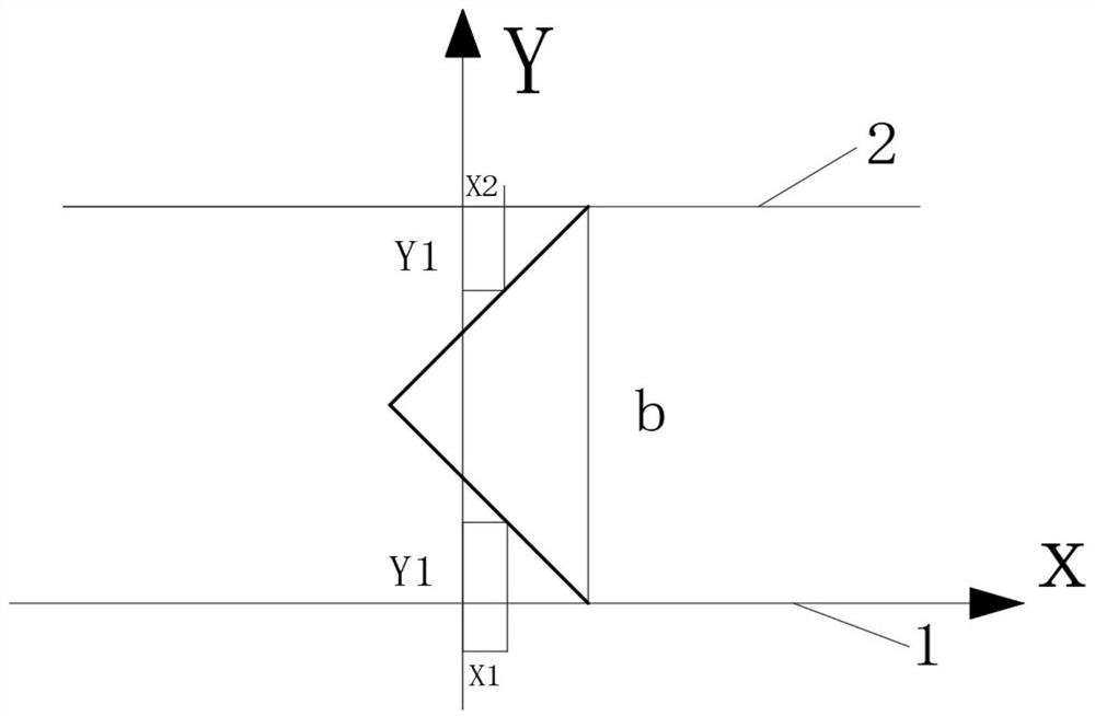
[0022] Step 1. Determination of the tool path, such as figure 2 Shown: After the tool setting is completed, the Z-axis and C-axis linkage tool of the machine tool moves in a spiral motion relative to the workpiece, moving from the lower end surface to the middle position, that is, from position 1 to position 3, and then from the middle position to the upper end surface, that is, from the From position 3 to position 2, the machining of the left tooth surface is completed. The tool moves to the next cutting position, and the Z-axis and C-axis linkage tool performs a spiral mo...


PUM


Abstract

The invention discloses a herringbone gear centering degree on-line measurement and correction method, which comprises the steps of determining a herringbone gear machining tool movement path; determining relevant parameters of a herringbone tooth, including a helical angle and a tooth width; determining a herringbone gear space coordinate system, wherein the lower end face of the herringbone gearserves as a space coordinate system XOZ plane, and the reference axis of a gear shaft coincides with the Y axis; recording coordinates of a tooth profile on the X axis when a cutter moves to the middle position from the lower end face and moves by Y1 distances in the Y-axis direction; when the cutter moves to the middle position from the upper end face, adopting the x-coordinate of the intersection point of the cutter and the tooth profile as X2 when the moving distance of the cutter in the Y direction is Y1, and obtaining a tangential centering degree error; and correcting the herringbone gear through the cutter. According to the herringbone gear centering degree on-line measurement and correction method provided by the invention, the centering error in the tangential direction of the gear is measured according to the change of the motion component of the cutter in the machining process, and the real-time measurement of the centering error is realized; and the end face of an existinggear serves as a benchmark, so that errors generated when a middle plane serves as the benchmark are avoided.

Description

technical field [0001] The invention relates to the technical field of measuring the centering error of a herringbone gear, in particular to a real-time detection method for the centering error of a herringbone gear during the processing of the herringbone gear. Background technique [0002] While the herringbone gear has the characteristics of helical gear transmission, it avoids the disadvantages of the helical gear in the transmission process. The herringbone gear can be regarded as a combination of two helical gears with opposite rotation directions. It is possible to balance the axial force added to a single helical gear. The herringbone gear has the characteristics of strong bearing capacity, small axial load, high transmission efficiency and stable transmission. Therefore, herringbone gear transmission is widely used in heavy machinery transmission systems such as forging equipment, petroleum machinery, and ships. At present, the processing of herringbone gears gene...

Claims


Application Information

Patent Timeline
Patent Type & Authority Applications(China)
IPC IPC(8): B23F7/00B23F23/00B23Q17/22
CPCB23F7/00B23F23/00B23Q17/22
Inventor 洪荣晶姚俊华
Owner NANJING UNIV OF TECH
Why Eureka
Try Eureka