Metal plate machining workbench

A metal plate and workbench technology, applied in the direction of workbench, manufacturing tools, etc., can solve the problems of metal plate bending deformation, easy side deviation phenomenon, affecting product quality, etc., to improve functionality, installability, structural design flexibility, The effect of reasonable structural design

Active Publication Date: 2021-03-12
WENLING ZHIYING ELECTRONICS TECH CO LTD
View PDF7 Cites 0 Cited by
  • Summary
  • Abstract
  • Description
  • Claims
  • Application Information

AI Technical Summary

Problems solved by technology

[0003] Some circular metal plates are prone to side deviation when they are clamped and stamped due to the curvature of the periphery, resulting in bending deformation of the metal plate obtained after stamping, which affects product quality. Therefore, it is urgent to design a A workbench for clamping round metal plates to prevent bending and deformation of the metal plate during punching

Method used


Image

  • Metal plate machining workbench
  • Metal plate machining workbench
  • Metal plate machining workbench

Examples


Embodiment Construction

[0030] The following is a clear and complete description of the technical solution of the patent of the present invention in conjunction with the accompanying drawings. Apparently, the described embodiments are part of the embodiments of the present invention, not all of them. Based on the embodiments of the present invention, all other embodiments obtained by those skilled in the art without creative efforts fall within the protection scope of the present invention.

[0031] In the description of the present invention, it should be noted that if the terms "center", "upper", "lower", "left", "right", "vertical", "horizontal", "inner", "outer" appear The orientation or positional relationship indicated by etc. is based on the orientation or positional relationship shown in the drawings, and is only for the convenience of describing the present invention and simplifying the description, rather than indicating or implying that the referred device or element must have a specific or...


PUM


Abstract

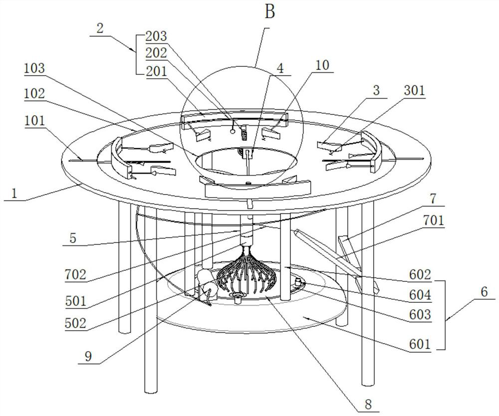
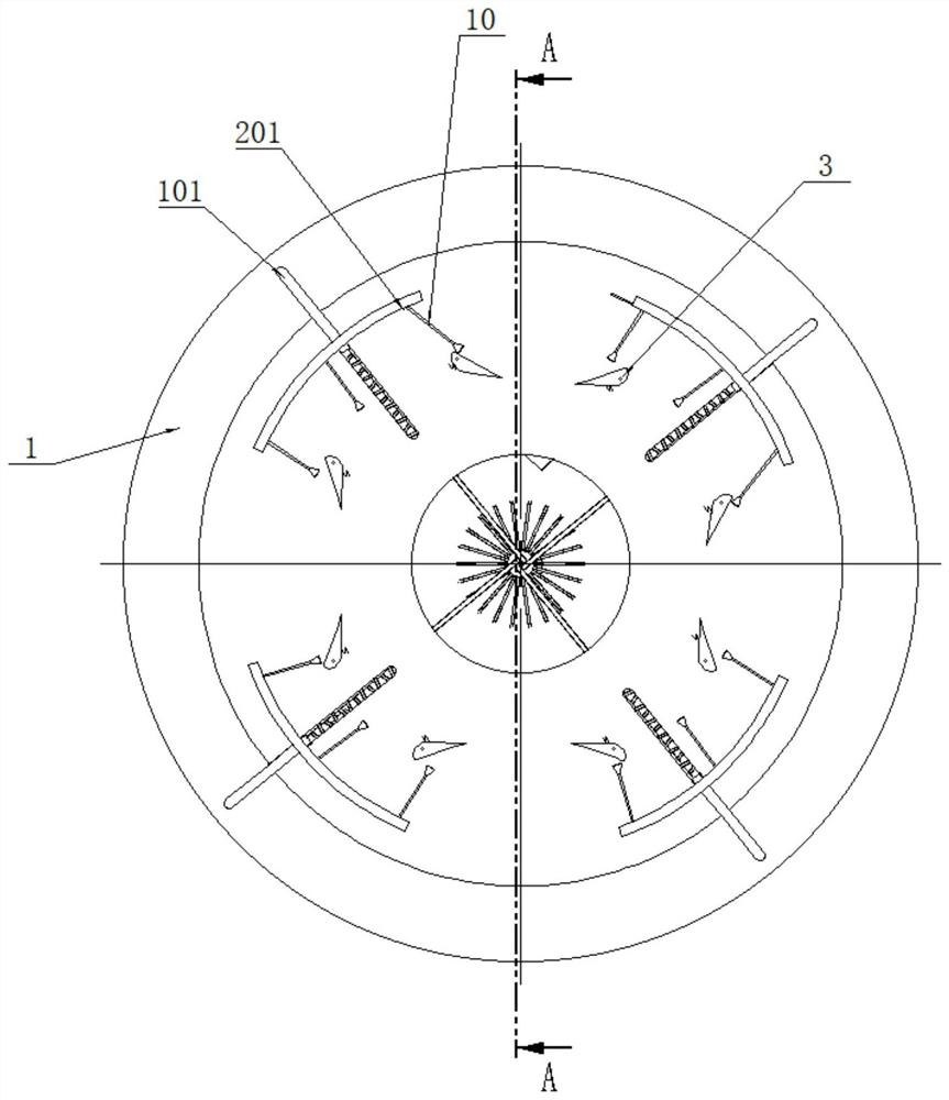
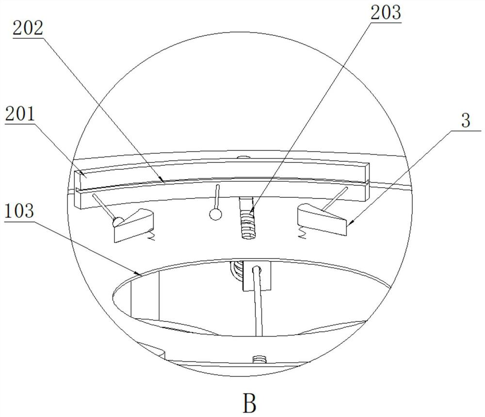
The invention relates to a metal plate machining workbench. The metal plate machining workbench comprises a pedestal; four clamping mechanisms and a rubber base are further arranged on the periphery and in the middle of the pedestal respectively; four pull ropes are arranged on the rubber base; the other ends of the pull ropes are connected to the clamping mechanisms; a cross beam is further arranged between two supporting rods at the bottom of the pedestal; a rotating shaft is arranged in the middle of the cross beam; a pedal is installed on the rotating shaft; the pedal is connected with therubber base through a steel chain arranged on the pedal, so that when the pedal is pressed downwards, the four clamping mechanisms are driven by the ropes to clamp a metal plate through the pull-downaction; the four clamping mechanisms are sequentially connected with the pedal in a pull rope connection mode; and in the actual use process, an operator only needs to step on the pedal to enable theround metal plate to be clamped in four directions; stress is concentrated after clamping; the metal plate clamped in the four directions is not prone to bending deformation when punched by punchingequipment; and therefore the metal plate machining workbench is suitable for clamping the round metal plate and is more reasonable in clamping structure.

Description

technical field [0001] The invention relates to the technical field of workbenches, in particular to a metal plate processing workbench. Background technique [0002] Expanded metal mesh refers to metal plates with various shapes and holes on the surface. The metal sheet is stamped and cold drawn by machine. After the sheet metal is stamped. The original length remains unchanged, but the width is 3 to 4 times larger than the original width. At present, the expanded metal mesh needs to be punched by a CNC punching machine in the process of processing, and the rectangular or square metal plate can be easily clamped on the CNC punching machine table. [0003] Some circular metal plates are prone to side deviation when they are clamped and stamped due to the curvature of the periphery, resulting in bending deformation of the metal plate obtained after stamping, which affects product quality. Therefore, it is urgent to design a A workbench for clamping round metal plates to p...

Claims


Application Information

Patent Timeline
Patent Type & Authority Applications(China)
IPC IPC(8): B25H1/08B25H1/00
CPCB25H1/00B25H1/08
Inventor 吴夕茜
Owner WENLING ZHIYING ELECTRONICS TECH CO LTD
Why Eureka
Try Eureka