
Moving mechanism of industrial robot

A technology of industrial robots and mobile mechanisms, applied in the direction of manipulators, manufacturing tools, etc., can solve problems such as the inability to meet the needs of multi-station position changes, limitations of mobile mechanisms, etc., to avoid excessive unnecessary actions, ensure effective docking, and action flow. Simple and flexible effects

Active Publication Date: 2021-03-12
SUZHOU AGV ROBOT CO LTD
View PDF5 Cites 3 Cited by
  • Summary
  • Abstract
  • Description
  • Claims
  • Application Information

AI Technical Summary

Problems solved by technology

[0004] The purpose of the embodiments of the present invention is to provide a moving mechanism for an industrial robot, which aims to solve the problem that the moving mechanism in the prior art is too limited and cannot meet the needs of multi-station position changes

Method used


Image

  • Moving mechanism of industrial robot
  • Moving mechanism of industrial robot
  • Moving mechanism of industrial robot

Examples


Embodiment Construction

[0033] In order to make the object, technical solution and advantages of the present invention clearer, the present invention will be further described in detail below in conjunction with the accompanying drawings and embodiments. It should be understood that the specific embodiments described here are only used to explain the present invention, not to limit the present invention.

[0034] The specific implementation of the present invention will be described in detail below in conjunction with specific embodiments.

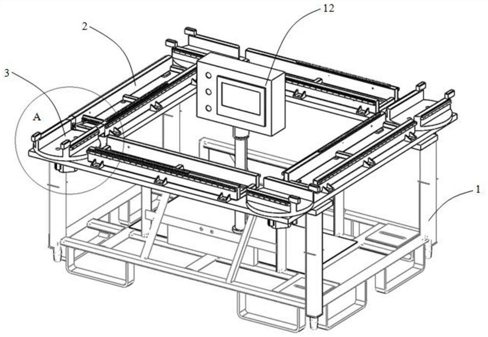
[0035] Such as figure 1 As shown, it is a structural diagram of a moving mechanism of an industrial robot provided by an embodiment of the present invention. The embodiment of the invention is achieved in this way, a moving mechanism of an industrial robot, the moving mechanism includes:

[0036] Mounting bracket 1;

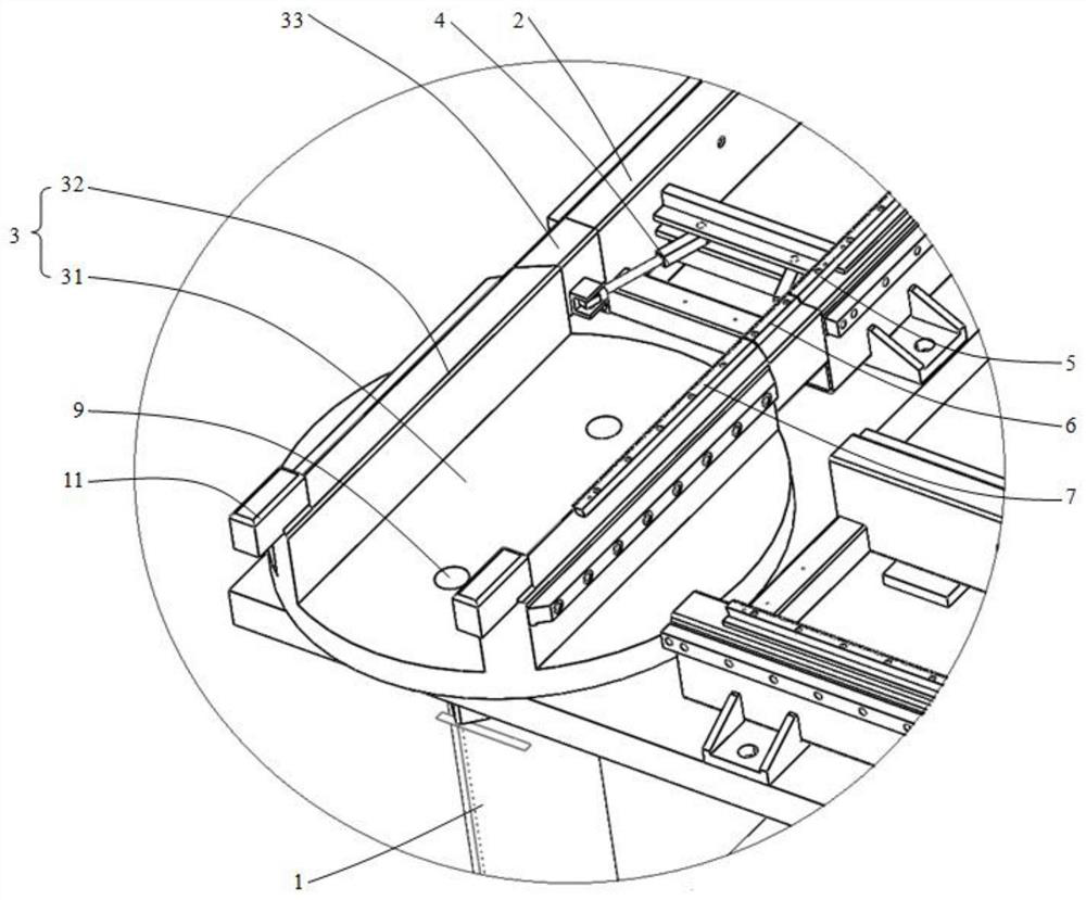
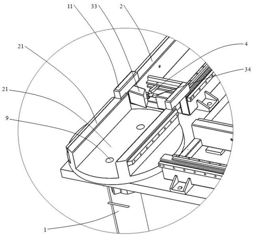
[0037] The moving track assembly is arranged on the mounting bracket 1 and includes at least two moving tracks 2 and at least one transfer mecha...


PUM


Abstract

The invention belongs to the technical field of industrial robot equipment, and discloses a moving mechanism of an industrial robot. The moving mechanism mainly comprises a mounting bracket and a moving track assembly; the moving track assembly is arranged on the mounting bracket and comprises at least two moving tracks and at least one robot transferring mechanism; and the transferring mechanismis arranged between the two ends of the two moving tracks and used for transferring the industrial robot of one moving track into the other moving track. According to the embodiment of the moving mechanism, the industrial robot in one moving track is transferred to the other moving track by arranging the transferring mechanism, so that the moving track switching of the industrial robot can be realized, the requirement of multi-station position change can be met, multiple robots do not need to be arranged between close or short-distance stations, station conversion can be effectively carried out, and the arrangement of the stations is not affected.

Description

technical field [0001] The invention belongs to the technical field of industrial robot equipment, and in particular relates to a moving mechanism of an industrial robot. Background technique [0002] In order to reduce the labor intensity of operators and improve work efficiency, enterprises are increasingly using industrial robots to replace humans in the process of production and transportation to complete some tasks with single labor content and high labor intensity; in order to facilitate movement, usually Industrial robots are set up movable by fixed rails. But generally speaking, only long and straight tracks can be used in the prior art. Since industrial robots basically use wheeled movement, non-linear tracks tend to generate greater friction with the wheels. In addition, the prior art Most industrial robots can only move on a single track, which cannot meet the needs of multi-station movement operations. [0003] It can be seen that the moving mechanism of the in...

Claims


Application Information

Patent Timeline
Patent Type & Authority Applications(China)
IPC IPC(8): B25J5/02B25J19/00
CPCB25J5/02B25J19/00
Inventor 张海英
Owner SUZHOU AGV ROBOT CO LTD
Learn More