Industrial batten slicing equipment
An industrial wood strip technology, which is applied in the field of industrial wood strip slicing equipment, can solve the problems of low efficiency, easy cutting of the knife to the operator, and the speed of operation, etc., to achieve the effect of avoiding random movement
- Summary
- Abstract
- Description
- Claims
- Application Information
AI Technical Summary
Problems solved by technology
Method used
Image

Examples
Embodiment 1
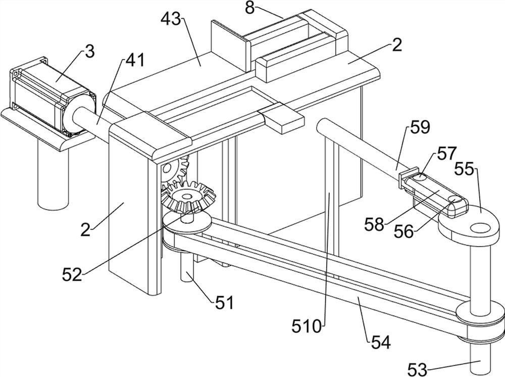
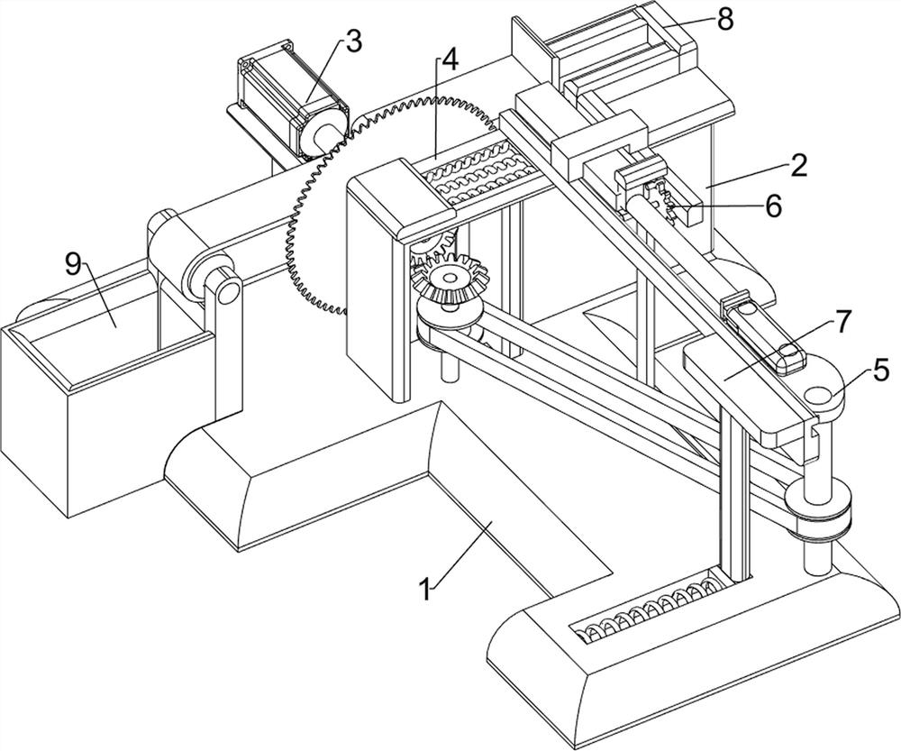
[0053] An industrial wood chipping equipment such as figure 1 , figure 2 , image 3 and Figure 5 As shown, it includes a bottom plate 1, a support frame 2, a servo motor 3, a cutting mechanism 4, a material pushing mechanism 5, a transmission mechanism 6 and a fixing mechanism 7, a support frame 2 is arranged in the middle of the top of the bottom plate 1, and a The servo motor 3, the output shaft of the servo motor 3 and the support frame 2 are provided with a cutting mechanism 4, the top of the bottom plate 1 is provided with a pushing mechanism 5, the bottom plate 1 and the top of the support frame 2 are provided with a fixing mechanism 7, the fixing mechanism 7 and the pushing mechanism The mechanism 5 is provided with a transmission mechanism 6 .
[0054] People can use the present invention to cut long wooden blocks. Firstly, the long wooden blocks are placed on the top of the conveying mechanism 6, and then the operator starts the servo motor 3. After the servo mot...
Embodiment 2
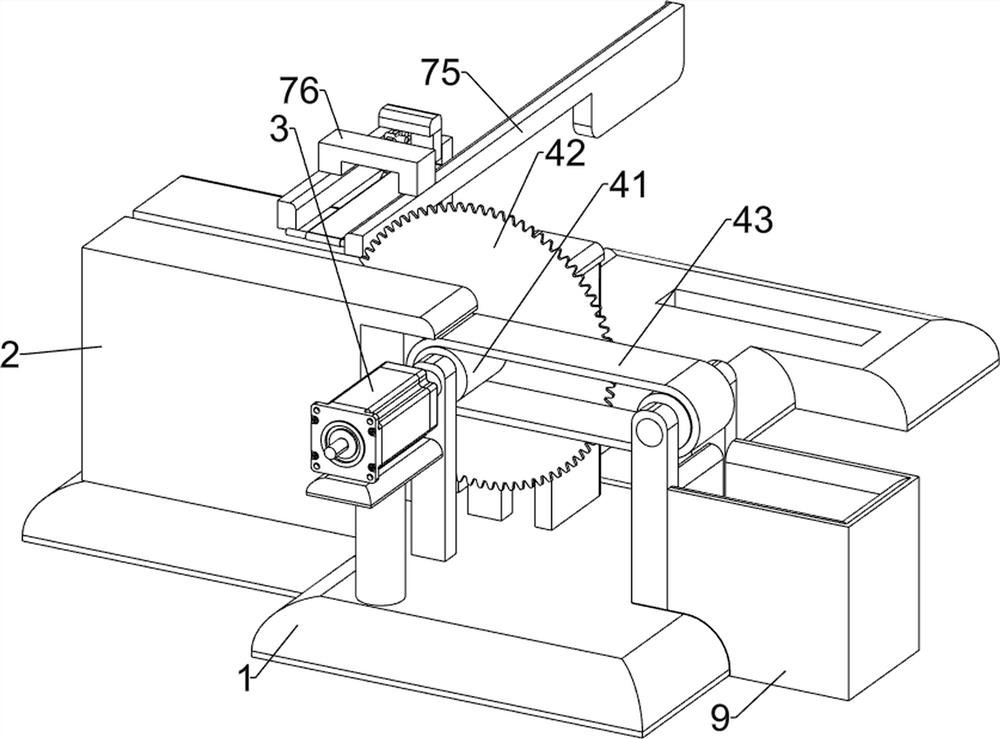
[0056] On the basis of Example 1, such as figure 1 , figure 2 , image 3 , Figure 4 and Figure 5 As shown, the cutting mechanism 4 includes a first rotating shaft 41, a blade 42 and a conveyor belt 43, the output shaft of the servo motor 3 is provided with a first rotating shaft 41, and the first rotating shaft 41 is rotationally connected with the middle part of the support frame 2, and the support frame 2 is left The side-rotating type is provided with a first rotating shaft 41 , a conveyor belt 43 is connected between the two first rotating shafts 41 , and a blade 42 is provided on the front side of the right first rotating shaft 41 .
[0057] The cutting mechanism 4 is used to cut long wooden strips, and drives the long wooden strips after cutting to be transported to the left for the operator to collect. First, the long wooden pieces are placed on the top of the conveying mechanism 6, and then the operator starts the servo motor 3, and the servo motor 3. After star...
Embodiment 3
[0065] On the basis of Example 2, such as figure 1 , figure 2 and Figure 5 As shown, it also includes a blanking push block 8 and a material receiving box 9, the fixed block 76 rear side is provided with a blanking push block 8, and the left part of the rear side of the base plate 1 is provided with a material receiving box 9, and the material receiving box 9 is located at the conveyor belt 43 left side.
[0066] The blanking push block 8 can realize promoting the long plank to move to the left, and the material receiving box 9 is used to collect the cut wooden blocks, and when the wooden block is cut, the blank push block 8 can follow the fixed block 76 to move to the left, Promote the block to move to the left, and then be pushed onto the conveyor belt 43, and then the conveyor belt 43 drives the block to move to the left, and the block is delivered to the receiving box 9.
PUM
 Abstract
Description
Claims
Application Information
 - Generate Ideas
- Intellectual Property
- Life Sciences
- Materials
- Tech Scout
- Unparalleled Data Quality
- Higher Quality Content
- 60% Fewer Hallucinations
Browse by: Latest US Patents, China's latest patents, Technical Efficacy Thesaurus, Application Domain, Technology Topic, Popular Technical Reports.
© 2025 PatSnap. All rights reserved.Legal|Privacy policy|Modern Slavery Act Transparency Statement|Sitemap|About US| Contact US: help@patsnap.com