A kind of automatic cartoning equipment for biocapsule production
A technology of automatic cartoning and biocapsules, applied in packaging, single object, transportation and packaging, etc., can solve problems such as time-consuming and laborious, and achieve the effect of saving labor costs and being easy to take out.
- Summary
- Abstract
- Description
- Claims
- Application Information
AI Technical Summary
Problems solved by technology
Method used
Image
Examples
Embodiment 1
[0077] An automatic cartoning equipment for the production of biological capsules, such as figure 1 As shown, it includes a base 1 , a placing mechanism 2 and a pushing mechanism 3 , a placing mechanism 2 is provided on the right side of the base 1 , and a pushing mechanism 3 is provided on the base 1 .
[0078] When people need to pack the biocapsules, first place the box on the components of the push mechanism 3, place the capsules on the components of the placement mechanism 2, and then control the components of the push mechanism 3, so that the capsules are boxed, and after completion, put the capsules into boxes. The capsule can be taken out.
Embodiment 2
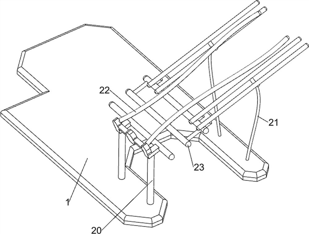
[0080] On the basis of Example 1, as Figure 2-3 As shown, the placing mechanism 2 includes a blocking frame 20, a placing frame 21, a pressure rod 22 and a bracket 23. The base 1 is provided with a blocking frame 20 on the right front side, and the base 1 is provided with two placing frames 21 on the right rear side. Both sides are connected with pressing rods 22 , and a bracket 23 is arranged between the front sides of the placing frame 21 .
[0081] When people need to pack the biocapsules, place the capsules between the placing rack 21 and the pressing rod 22. As the pushing mechanism 3 moves the capsules to the left, the capsules slide forward at intervals, so that the interval feeding can be realized. Effect.
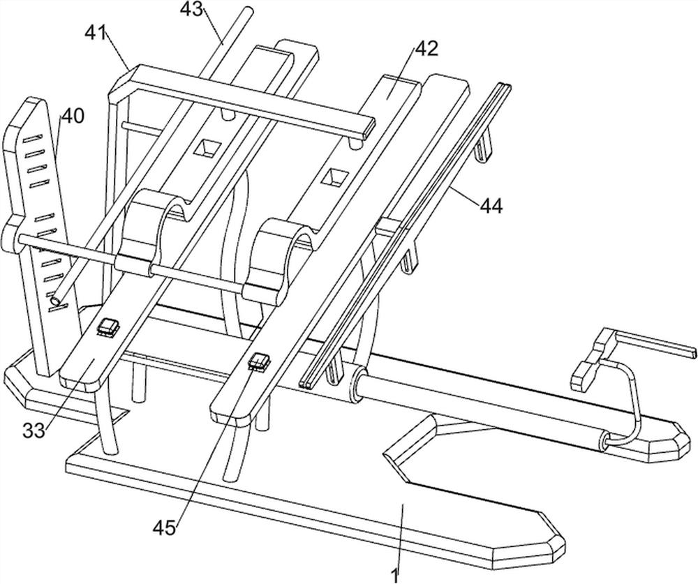
[0082] The push mechanism 3 includes an electric push rod 30, a push frame 31, a blocking rod 32 and a support frame 33. The left side of the base 1 is provided with an electric push rod 30, the right side of the electric push rod 30 is provided with a push frame...
Embodiment 3
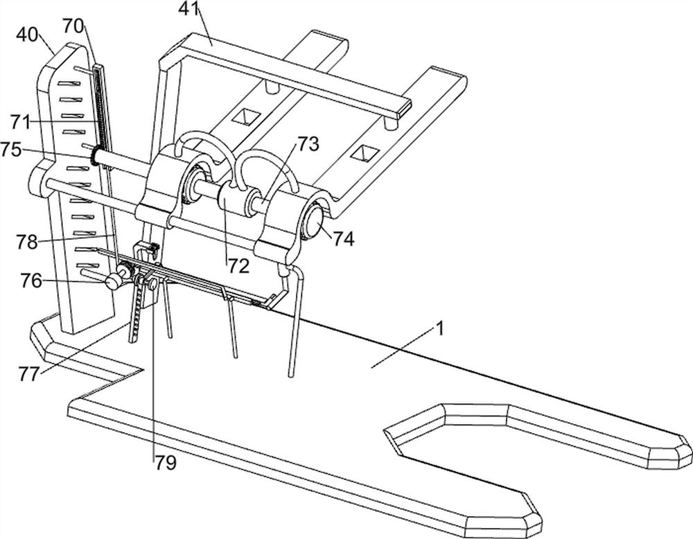
[0085] On the basis of Example 2, as Figure 4-10 As shown, it also includes a limit assembly 4, the limit assembly 4 includes a support plate 40, a mounting plate 41, a pressure plate 42, a limit rod 43, a limit slide 44, a U-shaped rod 45 and a tension spring 46, the base 1 The left front side is provided with a support plate 40, the left rear side of the base 1 is provided with a mounting plate 41, the upper left and right sides of the mounting plate 41 are connected with pressure plates 42, the front side of the pressure plate 42 is connected with the support plate 40, the support plate 40 and the mounting plate 41 are connected. There is a limit rod 43 between them, a limit slide 44 is provided on the right side of the support frame 33 on the right side, a U-shaped rod 45 is slidably connected between the top and front sides of the support frame 33, and the left and right sides of the U-shaped rod 45 are connected to the support frame 33. There are tension springs 46 betw...
PUM
 Abstract
Description
Claims
Application Information
 - R&D
- Intellectual Property
- Life Sciences
- Materials
- Tech Scout
- Unparalleled Data Quality
- Higher Quality Content
- 60% Fewer Hallucinations
Browse by: Latest US Patents, China's latest patents, Technical Efficacy Thesaurus, Application Domain, Technology Topic, Popular Technical Reports.
© 2025 PatSnap. All rights reserved.Legal|Privacy policy|Modern Slavery Act Transparency Statement|Sitemap|About US| Contact US: help@patsnap.com


