High-performance gate valve

A high-performance, gate valve technology, applied in the direction of valve details, valve devices, sliding valves, etc., can solve the problems of slow opening and closing speed, poor sealing performance of gate valves, etc., achieve fast opening and closing speed, good sealing performance, and improve opening and closing speed effect

Active Publication Date: 2021-03-12
HANGZHOU CHUNJIANG VALVE
View PDF12 Cites 2 Cited by
  • Summary
  • Abstract
  • Description
  • Claims
  • Application Information

AI Technical Summary

Problems solved by technology

[0003] The invention overcomes the disadvantages of poor sealing performance and slow opening and closing speed of the existing gate valve, and provides a high-performance gate valve with good sealing performance and fast opening and closing speed

Method used


Image

  • High-performance gate valve
  • High-performance gate valve
  • High-performance gate valve

Examples


Embodiment 1

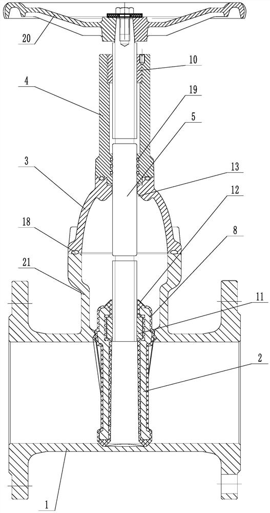
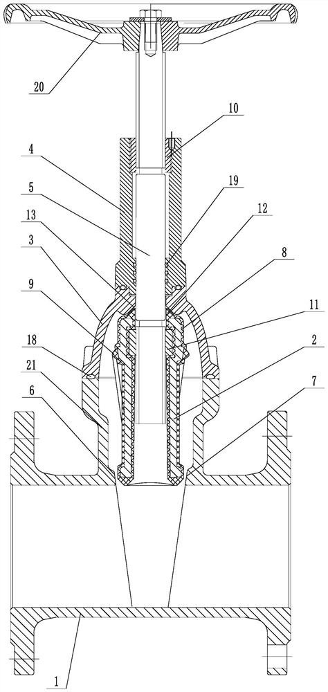
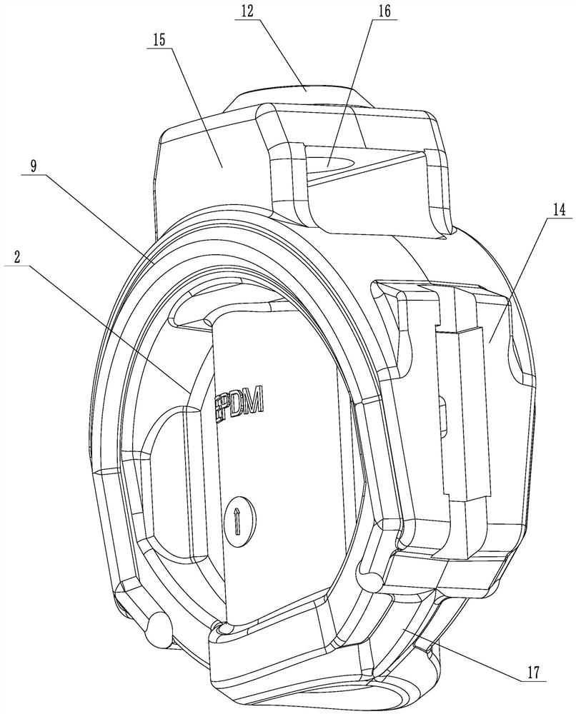
[0027] Embodiment 1: A kind of high-performance gate valve (see attached figure 1 , attached figure 2 , attached image 3 ), including valve body 1, gate plate 2, valve cover 3, bracket 4, the gate plate is adapted to be installed in the valve body, the valve cover is connected between the valve body and the bracket, the gate plate is connected to the valve stem 5, the valve body and the gate The corresponding position of the board is provided with a left sealing surface 6 and a right sealing surface 7. The outer surface of the gate is covered with a sealing layer 8. Both sides of the gate are provided with sealing protrusions 9. The two sealing protrusions are respectively sealed with the left sealing surface and the right sealing surface. The surface fits and seals; a bracket nut 10 is installed on the bracket, and a gate nut 11 is installed on the gate plate. The thread rotation direction of the bracket nut is opposite to that of the gate nut, and both the bracket nut and...

Embodiment 2

[0035] Embodiment 2: A kind of high-performance gate valve (see attached Figure 4 , attached Figure 5 , attached Image 6 ), its structure is similar to that of Embodiment 1, the main difference is that in this embodiment, a through hole is provided in the middle of the gate plate, the lower end of the valve stem is placed in the through hole, and a sealing boss 22 is provided on the inner wall of the valve corresponding to the through hole, A ring of sealing grooves 23 is provided on the edge of the sealing boss on the inner wall of the valve, and a chamfer 24 is provided at the opening of the lower end of the through hole. 25. The section of the sealing protruding ring is V-shaped, the chamfer closely fits on the surface of the sealing boss, and the sealing protruding ring closely fits in the sealing groove. A positioning column 26 is arranged on the sealing boss, and the lower part of the positioning column is rotated to install a swivel sleeve 27. The upper part of the...


PUM


Abstract

The invention discloses a high-performance gate valve and aims to overcome the defects that an existing gate valve is poor in sealing performance and low in opening and closing speed. The gate valve comprises a valve body, a gate plate, a valve deck and a support, wherein the gate plate is installed in the valve body in a matched mode, the valve deck is connected between the valve body and the support, a valve rod is connected to the gate plate, a left sealing face and a right sealing face are arranged in the valve body and correspond to the position of the gate plate, the outer surface of thegate plate is coated with a sealing layer, and sealing protrusions are arranged on the two sides of the gate plate. The two sealing protrusions are respectively attached and sealed with the left sealing face and the right sealing face. A support nut is installed on the support, a gate plate nut is installed on the gate plate, the thread turning direction of the support nut is opposite to that ofthe gate plate nut, and the support nut and the gate plate nut are both in threaded connection with the valve rod. The high-performance gate valve is good in sealing performance and high in opening and closing speed.

Description

technical field [0001] The present invention relates to valve technology, more specifically, it relates to a high-performance gate valve. Background technique [0002] The opening and closing part of the gate valve is the gate, and the movement direction of the gate is perpendicular to the direction of the fluid. The gate valve can only be fully opened and fully closed, and cannot be adjusted or throttled. The gate valve is sealed by the contact between the valve seat and the gate, and usually the sealing surface will be surfacing with metal materials to increase wear resistance. There are rigid gate valves and elastic gate valves. According to the different gate valves, gate valves are divided into rigid gate valves and elastic gate valves. Although there are many types of gate valves, many gate valves currently on the market have poor sealing performance and slow opening and closing speeds. Contents of the invention [0003] The invention overcomes the disadvantages of...

Claims


Application Information

Patent Timeline
Patent Type & Authority Applications(China)
IPC IPC(8): F16K3/14F16K3/30F16K27/04F16K27/08F16K31/60F16K41/04
CPCF16K3/14F16K3/30F16K27/047F16K27/08F16K31/60F16K41/04
Inventor 周云忠柴为民柴璐路远航王丽萍
Owner HANGZHOU CHUNJIANG VALVE
Why Eureka
Try Eureka