Slide door of machine tool

a technology of sliding door and machine tool, which is applied in the field of sliding door of machine tool, can solve the problems of limited mounting space for the power transmission mechanism around the door, abrasion and failure of the pulleys and the wire, and achieve the effect of enabling automation, fast opening and closing of the door, and avoiding abrasion and damag

Inactive Publication Date: 2016-01-28
FANUC LTD
View PDF20 Cites 2 Cited by
  • Summary
  • Abstract
  • Description
  • Claims
  • Application Information

AI Technical Summary

Benefits of technology

[0019]The present invention has the above configuration. Since the opening is opened and closed by two doors that slide, an opening width becomes wide. Besides, the doors are driven by the motor via the ball screws, thereby achieving fast opening and closing of the doors and enabling automation. In addition, since the doors are opened and closed via the ball screws, abrasion and damage are hardly caused, thereby making it possible to stably open and close the doors fast. Further, since respective ball screws are disposed in parallel so as to open and close two slide doors and a slide direction of the doors is the same as an axial direction of the ball screws, a mounting space can be made compact with less wasteful space.

Problems solved by technology

In the meantime, a mounting space for the power transmission mechanism is limited around the door because a control device of the machine tool and the door may be provided in a double manner.
This causes such a problem that a large load is applied to the wire and the pulleys, which may highly possibly cause abrasion and failure of the pulleys and the wire.

Method used


Image

  • Slide door of machine tool
  • Slide door of machine tool
  • Slide door of machine tool

Examples


first embodiment

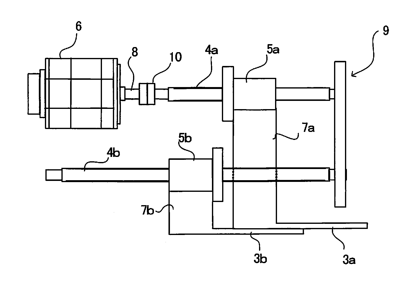
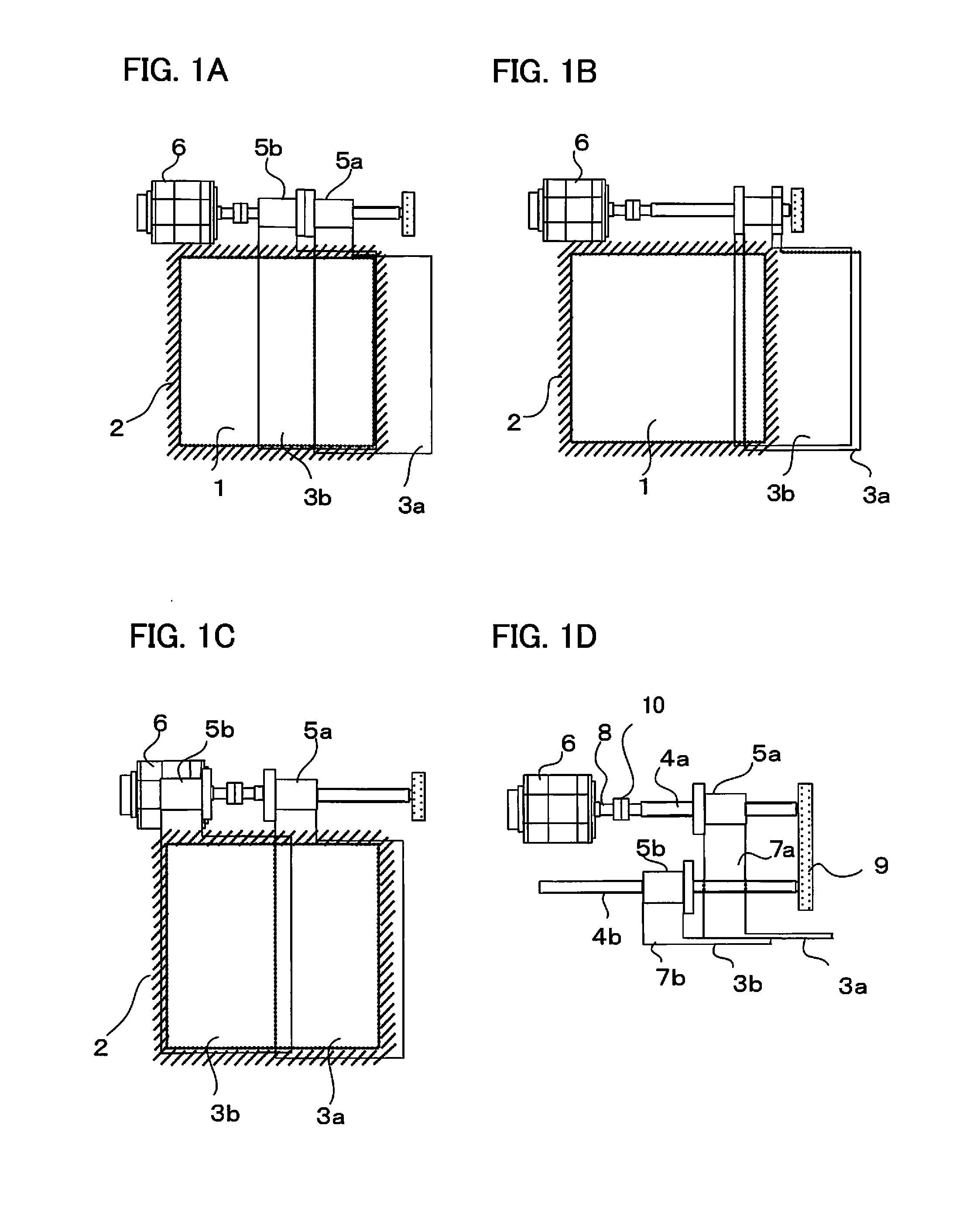
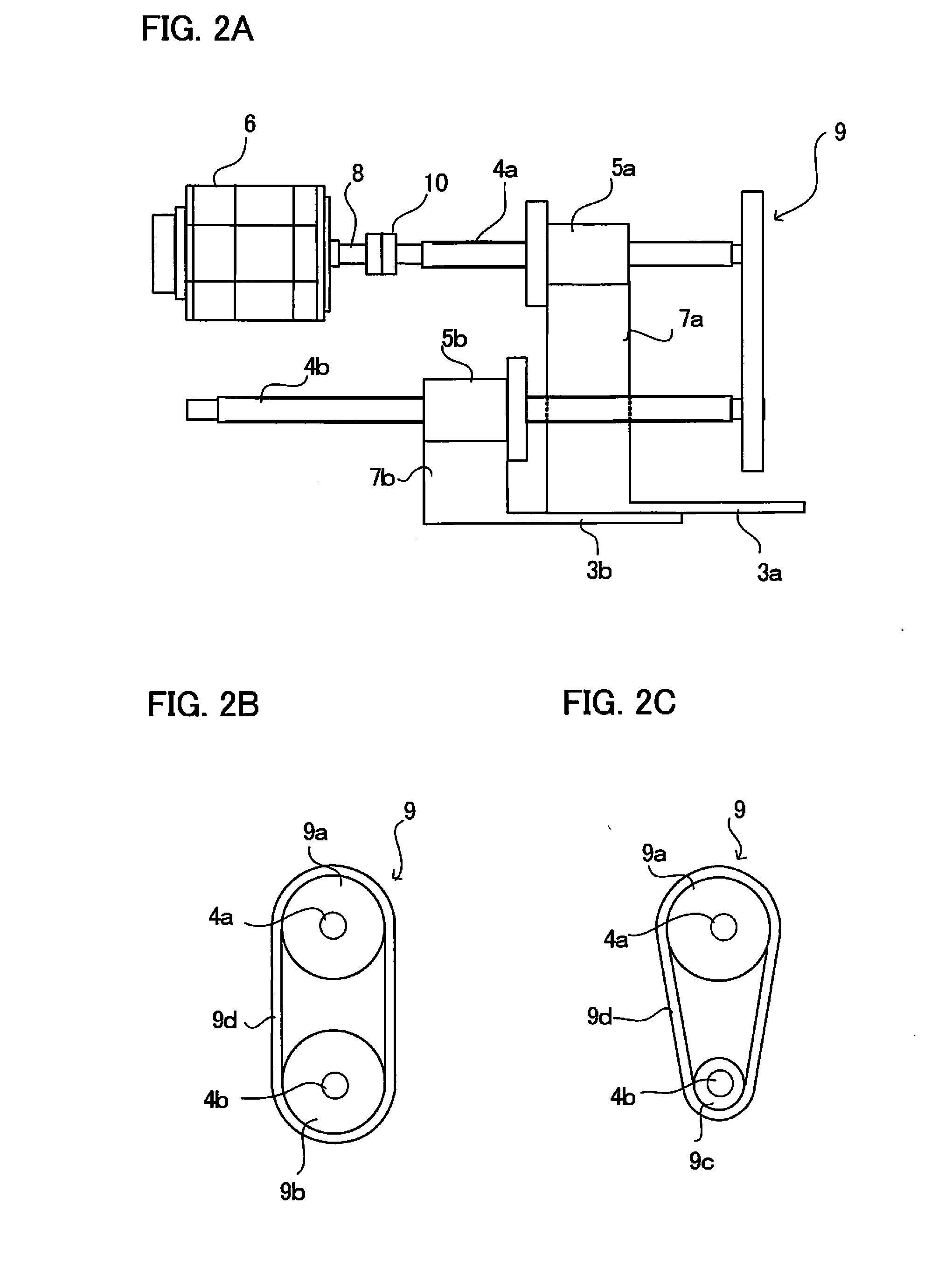
[0028]FIGS. 1A, 1B, 1C, 1D are schematic diagrams each illustrating a first embodiment of the present invention. FIGS. 1A, 1B, 1C are front views: FIG. 1A illustrates a state where an opening is opened halfway; FIG. 1B illustrates a state where the opening is opened fully; and FIG. 1C illustrates a state where the opening is closed. Further, FIG. 1D is a plane view.

[0029]A machining space in which a workpiece is cut with a cutter is covered with a fixed cover 2, and first and second doors 3a, 3b for opening and closing an opening 1 provided in the fixed cover 2 is provided. Two ball screws, i.e., first and second ball screws 4a, 4b are disposed in parallel with each other on an upper side relative to the first and second doors 3a, 3b, and a first nut 5a and a second nut 5b are engaged threadedly to the first ball screw 4a and the second ball screw 4b, respectively. An extension member 7a of the first door 3a is fixed to the first nut 5a, and an extension member 7b of the second door...

second embodiment

[0041]FIG. 4 is a schematic diagram of a second embodiment.

[0042]In the second embodiment, a driving motor is provided for each ball screw instead of providing the power transmission mechanism. The other configuration is the same as in the first embodiment.

[0043]A motor shaft 8a of a first motor 6a is connected to a first ball screw 4a via a shaft coupling 10a with their shaft centers being aligned. A motor shaft 8b of a second motor 6b is connected to a second ball screw 4b via a shaft coupling 10b with their shaft centers being aligned. Except that the power transmission mechanism 9 is not provided, the other configuration is the same as in the first embodiment, so a description thereof is omitted.

[0044]A first door 3a is driven by the first motor 6a via the first ball screw 4a and a nut 5a. A second door 3b is driven by the second motor 6b via the second ball screw 4b and a nut 5b. Since the doors 3a, 3b are driven by independent motors 6a, 6b, respectively, stroke amounts, movin...

third embodiment

[0046]In the first and second embodiments described above, two doors are moved in the same direction so as to open and close the opening. However, in the third embodiment, two doors are moved in opposite directions so as to open and close an opening.

[0047]FIGS. 5A, 5B are schematic diagrams each illustrating a first aspect of the third embodiment: FIG. 5A is a plan view; and FIG. 5B is a front view. A first ball screw 4a is connected to a motor shaft of a motor 6 via a shaft coupling 10 with its shaft center being aligned with a shaft center of the motor. Further, the first ball screw 4a is connected to a second ball screw 4b via a power transmission mechanism 9. An extension member 7a of a first door 3a is fixed to a first nut 5a engaged threadedly to the first ball screw 4a. Further, an extension member 7b of a second door 3b is fixed to a second nut 5b engaged threadedly to the second ball screw 4b. FIGS. 5A, B illustrate a state where an opening is closed by two doors 3a, 3b. Wh...


PUM


Abstract

A slide door of a machine tool which slide door is constituted by first and second doors for opening and closing, in a sliding manner, an opening of the machine tool includes: a first nut fixed to the first door; a first ball screw engaged threadedly to the first nut; a second ball screw placed in parallel with the first ball screw; a second nut engaged threadedly to the second ball screw and fixed to the second door is fixed thereto; and a motor for driving the first and second ball screws via a power transmission mechanism.

Description

BACKGROUND OF THE INVENTION[0001]1. Field of the Invention[0002]The present invention relates to a door provided in a cover for covering a machining space in which a workpiece is cut in a machine tool.[0003]2. Description of the Related Art[0004]In a machine tool, chips caused in cutting and a coolant discharged to a machining region are scattered all over. In order to prevent the scattering outside the machine tool, a machining space is covered with a cover. In the meantime, it is necessary to access the machining space so as to take a workpiece in and out of the machining space, an opening may be provided in the cover and a slide door may be provided so as to close the opening.[0005]In a case of a large-sized workpiece, it is necessary to widen an opening width by the door. In view of this, a two-stage slide door is advantageous. Japanese Patent Application Publication No. 2006-205337 describes an example in which a two-stage slide door is provided in a machine tool. An upper end ...

Claims


Application Information

Patent Timeline
Patent Type & Authority Applications(United States)
IPC IPC(8): E05F15/652E06B3/46
CPCE05F15/652E05Y2900/608E06B3/46B23Q11/0078B23Q11/08B23Q11/0891
Inventor NAGAO, AKIHIKO
Owner FANUC LTD
Why Eureka
Try Eureka