
A six-degree-of-freedom platform and its application

A technology with a degree of freedom and a platform, which is applied in the directions of machines/supports, program-controlled manipulators, servo motors, etc., can solve the problems of hydraulic system impact and movement speed that cannot meet the work requirements, so as to achieve stable work, increase service life, and meet the requirements of the work. The effect of high speed requirements

Active Publication Date: 2022-01-07
HUAZHONG UNIV OF SCI & TECH
View PDF0 Cites 0 Cited by
  • Summary
  • Abstract
  • Description
  • Claims
  • Application Information

AI Technical Summary

Problems solved by technology

[0005] Aiming at the above defects or improvement needs of the prior art, the present invention provides a six-degree-of-freedom platform and its application, the purpose of which is to use the hinge structure formed by the first hinge beam and the second hinge beam to realize the hydraulic cylinder piston rod The speed of linear motion is amplified to ensure the stable and safe operation of the hydraulic cylinder and increase the service life of the hydraulic cylinder. This solves the problem that the movement speed of the piston rod of the hydraulic cylinder cannot meet the working requirements under high-speed and heavy-load conditions. Excessive speed will cause hydraulic pressure A technical problem with a large impact on the system

Method used


Image

  • A six-degree-of-freedom platform and its application
  • A six-degree-of-freedom platform and its application
  • A six-degree-of-freedom platform and its application

Examples


Embodiment Construction

[0033] In order to make the object, technical solution and advantages of the present invention clearer, the present invention will be further described in detail below in conjunction with the accompanying drawings and embodiments. It should be understood that the specific embodiments described here are only used to explain the present invention, not to limit the present invention. In addition, the technical features involved in the various embodiments of the present invention described below can be combined with each other as long as they do not constitute a conflict with each other.

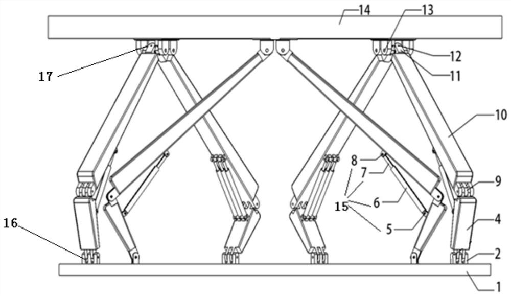
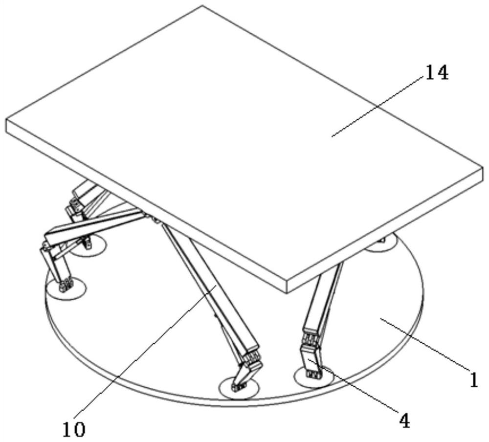
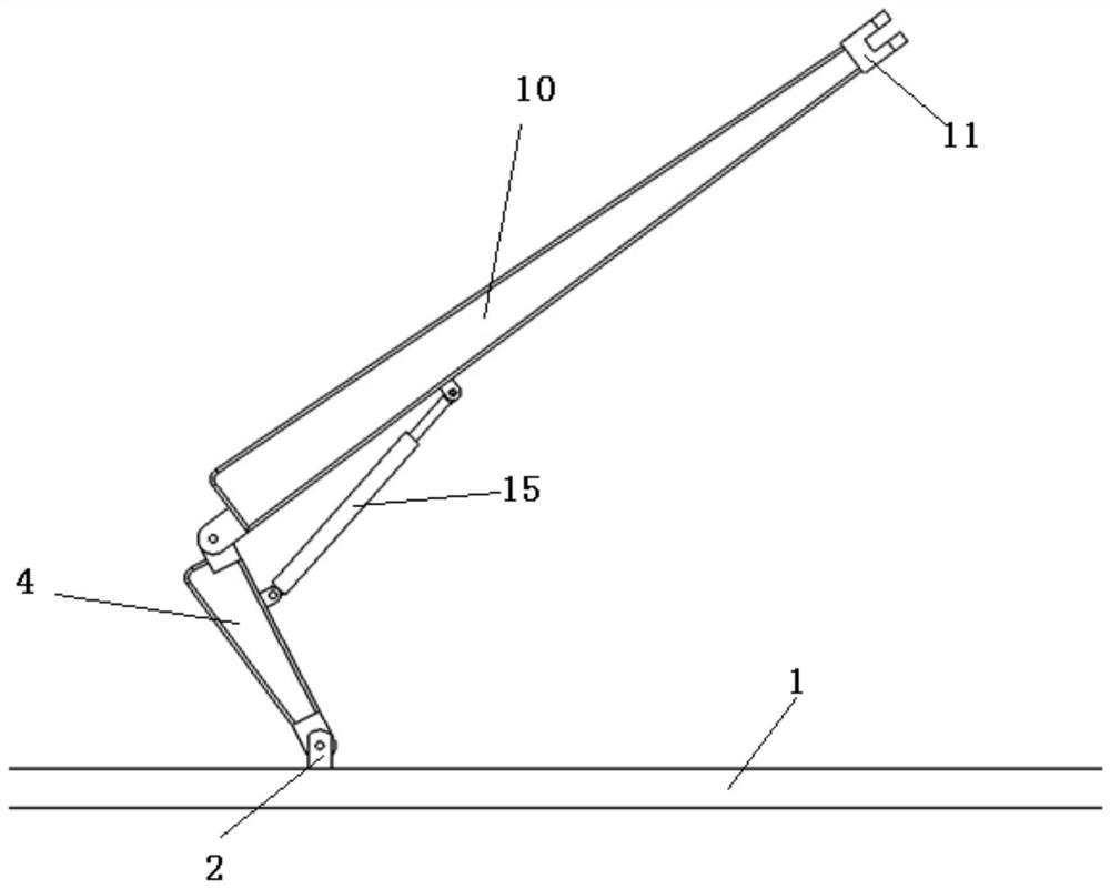
[0034] An embodiment of the present invention provides a six-degree-of-freedom platform, see figure 1 with figure 2 , including: a base 1, a moving platform 14, 6 driving devices connecting the base 1 and the moving platform 14, the 6 driving devices are used to drive the moving platform 14 to complete the movement of six degrees of freedom;

[0035] Wherein, any one of the driving devices in...


PUM


Abstract

The invention belongs to the technical field of six-degree-of-freedom mechanical structures, and more specifically relates to a six-degree-of-freedom platform and its application. The six-degree-of-freedom platform includes: a base, a moving platform, and six driving devices connecting the base and the moving platform, and any one of the six driving devices is used to drive the moving platform to complete the movement of six degrees of freedom; The driving device includes a hydraulic cylinder, a first hinge beam, and a second hinge beam hinged to the first hinge beam. One end of the hydraulic cylinder is connected to the first hinge beam, and the other end is connected to the second hinge beam. The connection is used to change the angle between the first hinge beam and the second hinge beam; the first hinge beam and the second hinge beam are respectively connected in rotation with the base and the moving platform. The invention utilizes the hinge structure formed by the first hinge beam and the second hinge beam to realize the speed amplification of the linear motion of the piston rod of the hydraulic cylinder, so as to ensure the stable and safe operation of the hydraulic cylinder and increase the service life of the hydraulic cylinder.

Description

technical field [0001] The invention belongs to the technical field of six-degree-of-freedom mechanical structures, and more specifically relates to a six-degree-of-freedom platform and its application. Background technique [0002] The six-degree-of-freedom platform can realize six-degree-of-freedom movement in space, thereby simulating various space motion attitudes, and can be widely used in various training simulators, such as flight simulators, car driving simulators, earthquake simulators and Dynamic movies, entertainment equipment and other fields. In the processing industry, it can be made into six-axis linkage machine tools, robots, etc. [0003] At present, the hydraulically driven six-degree-of-freedom platform structure in the prior art is composed of a base, a moving platform, a hinge mounting seat for the base and the moving platform, and six hydraulic cylinders. The base is fixed relative to the ground, and the six hydraulic cylinders are linear hydraulic cy...

Claims


Application Information

Patent Timeline
Patent Type & Authority Patents(China)
IPC IPC(8): B25J9/00F16M11/04F16M11/12F16M11/18F15B11/024F15B15/20
CPCF16M11/045F16M11/046F16M11/048F16M11/12F16M11/18F15B11/024F15B15/20
Inventor 李维嘉何宇航吴耀中谭洁姜志强刘法佑
Owner HUAZHONG UNIV OF SCI & TECH
Learn More